EUKYX-199-5100_G5S2_Instruction_Vol5_E.pdf - 第116页
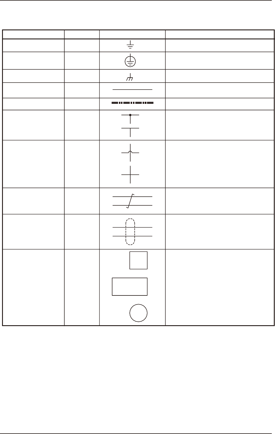
EUKYX 4-1 199-5100 1. Electrical and Electronic Symbols 1. Electr ic al a nd Electr on ic S ymbol s Name Symbols Graphical Symbols Remarks Grounding (General) Protective Ground Connection (Chassis) Cable W Optical Fiber …

199-5100
Chapter 4
Circuit Diagrams
This chapter describes the circuit diagrams.
As this contains highly sophisticated contents, it should carefully
be referred to.
1. Electrical and Electronic Symbols
2. Circuit Diagrams
EUKYX
EUKYX
4-1199-5100
1. Electrical and Electronic Symbols
1. Electrical and Electronic Symbols
Name
Symbols
Graphical Symbols Remarks
Grounding (General)
Protective Ground
Connection (Chassis)
Cable
W
Optical Fiber Cable
Connection
No Connection
Twisted Pair
Shielding
Equipment or Device
“W” is used only for signal wires in block
diagrams.
The cables are connected electrically.
The cables are not connected electrically.
Signal wires are twisted.
Shielded Wires
(a)
(b)
(c)
EUKYX
4-2199-5100
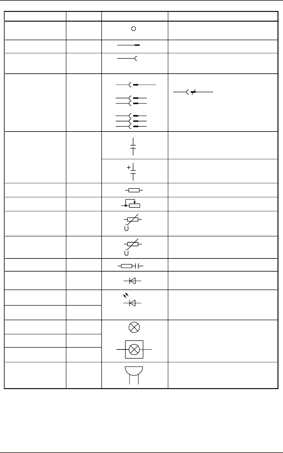
1. Electrical and Electronic Symbols
Name
Terminal
The left figure shows a
connector with multi-
poles. “n” is the
number of poles.
X
X
X
X
C
Polar Capacitor
The graphical symbol (light emitting
diode) is used to represent the light
emitting diodes in illuminating switches
and indicator lamps.
This represents a general electric lamp
used in an indicator lamp, an indicator,
etc.
R
R
R
Z
Z
V
H
H
E
E
H
Plug
Jack Socket
Resistance or
Resistor
Variable Resistor
Voltage-Dependent
Resistor
Varistor
Surge Killer
Diode
Indicator Lamp
Indicator Lamp
Recognition Lighting
Lighting Device
Buzzer
Light Emitting Diode
(General)
Electrostatic Capacity
or Capacitor
Capacitor (Polarity)
Plug, Jack Socket
Connector
(Combination of
Plug and Jack)
Nylon Connector
Symbols
Graphical Symbols Remarks
Double-
Pole
Triple-
Pole
n