EUKYX-199-5100_G5S2_Instruction_Vol5_E.pdf - 第121页
EUKYX 4-6 199-5100 1. Electrical and Electronic Symbols Name Solenoid V alve Y Y S B B B P P F V NPN PNP Solenoid The solenoid in the left figure is used for the electromagnetic lock-type door switches. V acuum Sensor Pr…
EUKYX
4-5199-5100
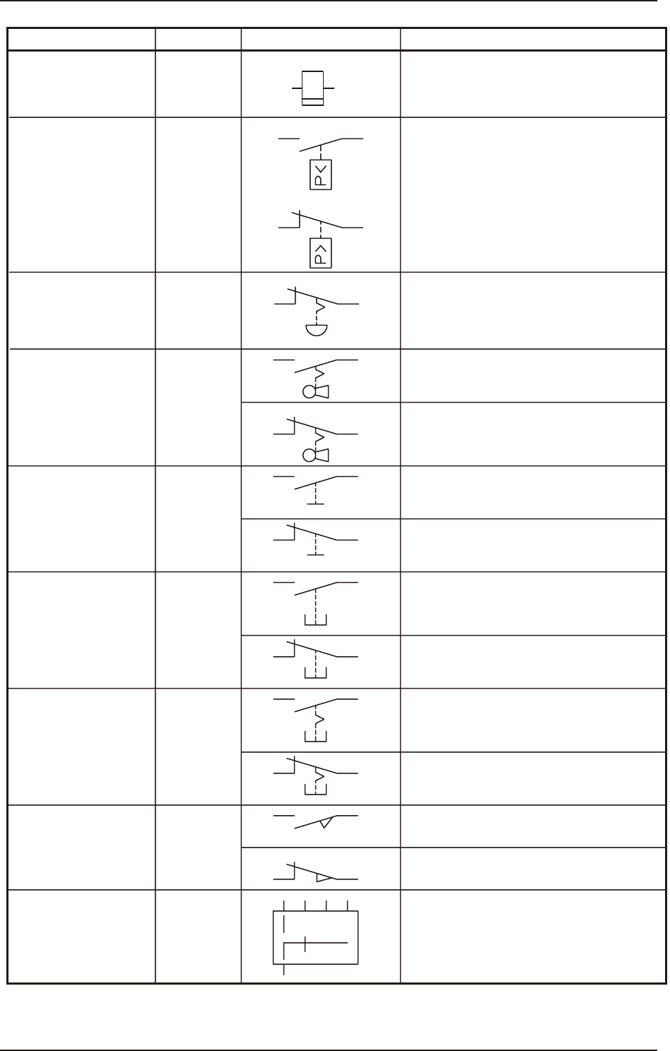
1. Electrical and Electronic Symbols
Name
Cycle Counter
Pressure Switch S
(a)
(b)
S
S
Key Switch
Contact a
Contact a
Contact a
Contact a
Contact a
Contact b
Contact b
Contact b
Contact b
The theory of contact combination
is described near the graphical symbol.
Contact b
Toggle Switch
Pushbutton Switch
(Momentary)
Pushbutton Switch
(Alternate)
Safety Door Switch
Limit Switch
Selector Switch
Emergency Stop
Button
Symbols
Graphical Symbols Remarks
S
S
S
S
S
EUKYX
4-6199-5100
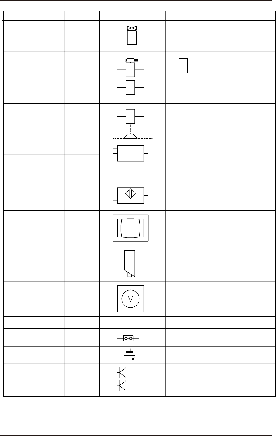
1. Electrical and Electronic Symbols
Name
Solenoid Valve
Y
Y
S
B
B
B
P
P
F
V
NPN
PNP
Solenoid
The solenoid in the left
figure is used for the
electromagnetic lock-type
door switches.
Vacuum Sensor
Proximity Sensor
Camera
Voltmeter
Measuring Instrument
Jumper
The left figure represents a jumper
socket (jumper mounting) in a unit PCB.
Battery
Transistor
Monitor Display
Touch Screen
Photosensor
Position Switch
Electromagnetic
Break (OFF Break)
Symbols
Graphical Symbols Remarks
EUKYX
4-7199-5100
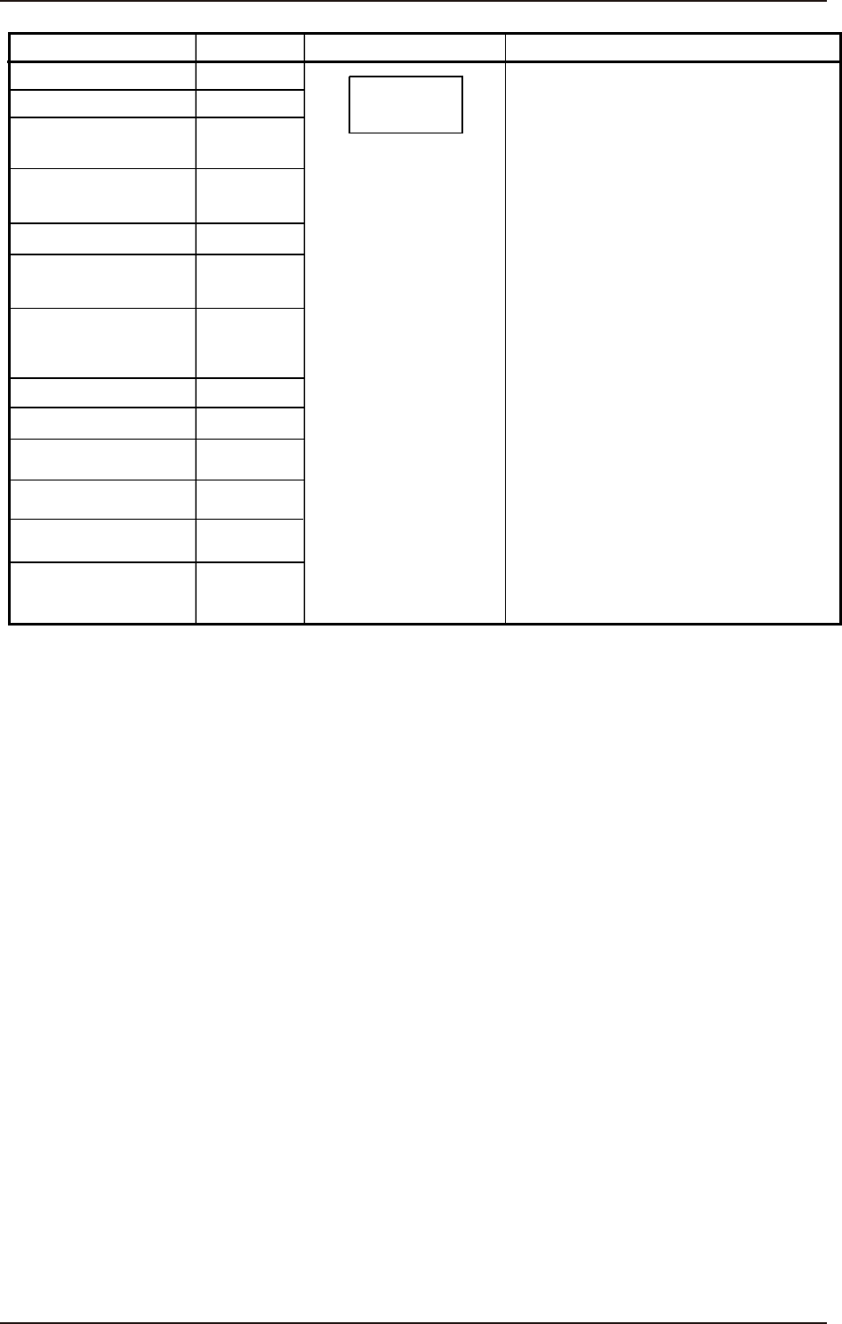
1. Electrical and Electronic Symbols
Name
Noise Filter
The graphical symbol generally
represents a unit.
Different circuit symbols are used
according to the classification of
electrical components.
Z
A
A
A
G
G
F
U
U
U
D
D
A
Servomotor Driver
Stepping Motor Driver
Speed Control Pack
Switching Power
Inverter
Converter
Unit PCB
Hard Disk Drive
Floppy Disk Drive
Other Units
Break Power for
Servomotor
Lightning Surge
Protector Fuse
Symbols
Graphical Symbols Remarks