OCP-02502-G.pdf - 第25页
VITRONICS REFLOW SOLDERING SYSTEMS EM 02502- G 15-Nov-00 (c) PAGE Operator’s Manual 24 MANUAL RAIL WIDTH ADJUST MENT The manual rail width adjustment must be enabled in the Oven Program to be able to adjust the Rail Widt…
VITRONICS REFLOW SOLDERING SYSTEMS
EM 02502-G 15-Nov-00 (c) PAGE Operator’s Manual
23
OVEN FEATURES AND OPTIONS
SOME OPTIONS IN THIS SECTION DO NOT EXIST ON ALL OVENS !!
See the Drawings & Data Section of the Oven Manuals to determine
which Options exist on your Oven
RAIL WIDTH ADJUSTMENT
The Rail width may be adjusted manually or by the optional automatic rail width
adjust.
When Product is started, the rail width may be adjusted. During the rail width
adjustment, all non-severe alarms and severe warnings are disabled. They are re-
enabled when the rail width adjustment is complete.
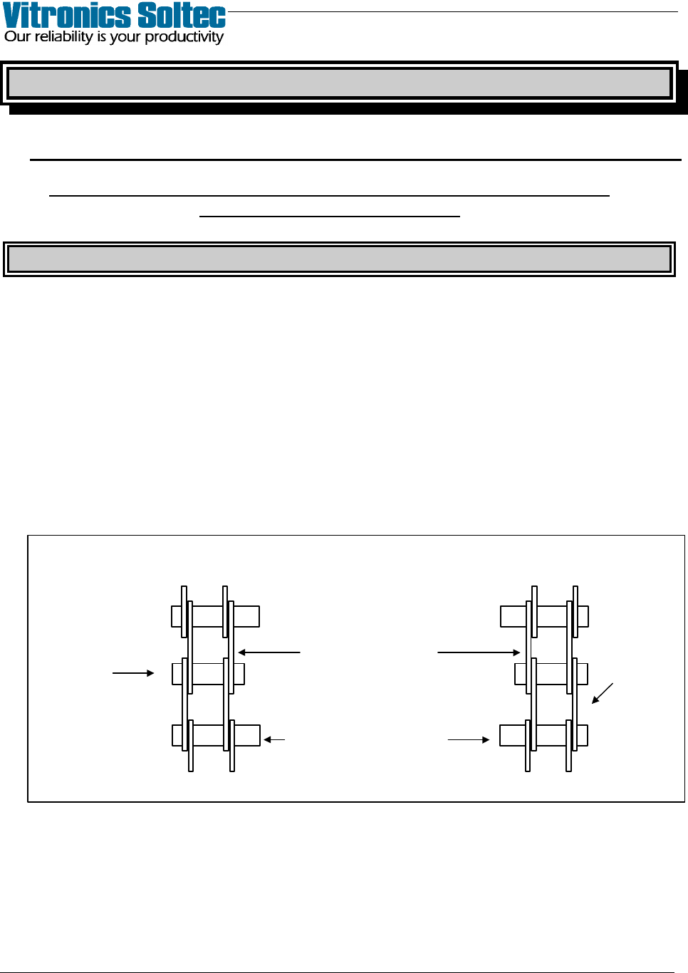
Rail width accuracy is important, use a test board to set up for accurate width
adjustment. The boards should rest on the chain pins and slide freely along the
conveyor without binding by rotating or jamming against the conveyor chain.
The dimensions for setting up the rail width should be measured between the walls
of the chain. See illustration below.
RAIL WIDTH
CHAIN CHAIN
EXTENDED PINS
Rail Width Measurement Illustration
VITRONICS REFLOW SOLDERING SYSTEMS
EM 02502-G 15-Nov-00 (c) PAGE Operator’s Manual
24
MANUAL RAIL WIDTH ADJUSTMENT
The manual rail width adjustment must be enabled in the Oven Program to be able
to adjust the Rail Width.
CAUTION
CONFIRM THAT NO BOARDS ARE BEING TRANSPORTED
BY THE CONVEYOR BEFORE CONTINUING.
BOARDS REMAINING ON THE CONVEYOR DURING ADJUSTMENT MAY
BE DAMAGED OR FALL ONTO A HEATER CELL, OR THE RAIL
SYSTEM MAY BE DAMAGED
The conveyor speed will increase to the maximum calibrated value and the rail
width can be adjusted using the switch located on the control panel at Offload end
of the oven. If the oven is fitted with automatic rail width adjustment, but the rail
width has been adjusted manually, the rail width alarm is disabled during manual
adjustment. (An alarm will be displayed if the new manually adjusted width
exceeds the Alarm Setpoints)
AUTOMATIC RAIL WIDTH ADJUSTMENT
NOTE: Ovens with automatic rail width adjust may have the rail width adjusted
manually. Refer to Manual Rail Width Adjustment, above.
Ovens with the auto rail width adjustment option will automatically adjust the rails
to the product width value specified in the PRODUCT description when a
PRODUCT is started unless the Manual Rail Adjust is selected in the Start-up
Wizard Dialogue Box …or…”No Rail Adjust was selected in the PRODUCT
description)
The automatic rail width system must be calibrated before it is used.
Refer to Auto Rail Width Calibration.
Automatic rail width adjustment occurs only when starting a PROCESS.
Refer to Start a Product or Recipe.
VITRONICS REFLOW SOLDERING SYSTEMS
EM 02502-G 15-Nov-00 (c) PAGE Operator’s Manual
25
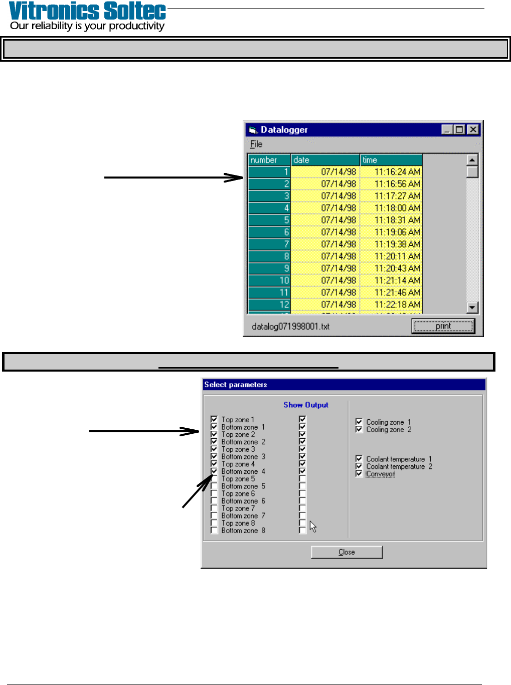
DATALOG
The Datalog keeps a record of set point measured values and output values, and is
periodically recorded. The record is stored on the hard disk and cannot be erased within
the Oven Control Program. When the space allocated for the datalog files is full, the
oldest entries are discarded.
Viewing and/or printing the Datalog is
achieved by selecting Log, then View,
then Datalog, to display the Datalog
Dialogue Box:
(The columns can be stretched to display
information as desired)
PRINT will sent ALL the data in the
DATALOG files to a connected printer,
or to disk by selecting “Print to file” in
the “Print Dialog Box”. (See “Printing” in
Table of Contents) The print-out range
is NOT selectable)
DATALOG ENTRY DESCRIPTIONS
At the Main Pull-Down Menu,
select: Log, View, Data Log, File,
and Select Parameters to display
this Dialogue Box.
The Datalogger records ALL
events listed in this Dialogue Box,
however, which ones are
displayed for viewing is selectable
by ‘clicking’ the small white boxes
to display the check-marks