OCP-02502-G.pdf - 第9页
VITRONICS REFLOW SOLDERING SYSTEMS EM 02502- G 15-Nov-00 (c) PAGE Operator’s Manual 8 . OPER ATING SCREEN , MENUS, DIALOGUE BOXES, & SYMBOLS The operating screen is shown here with an XPM-Series XN0820 Oven in Operat…
Restart Process
Start New Process
Stop Running Process
Save As
Alarm Log
Datalog
Trend
Profile
DELETE LOG FILES
Printer Setup
Product/Recipe Editor
Product/Recipe Files
Database
Profiles
Import
(OS2 files)
Login
Access Control
(modify passwords)
Demo Mode
Exit
(leave program)
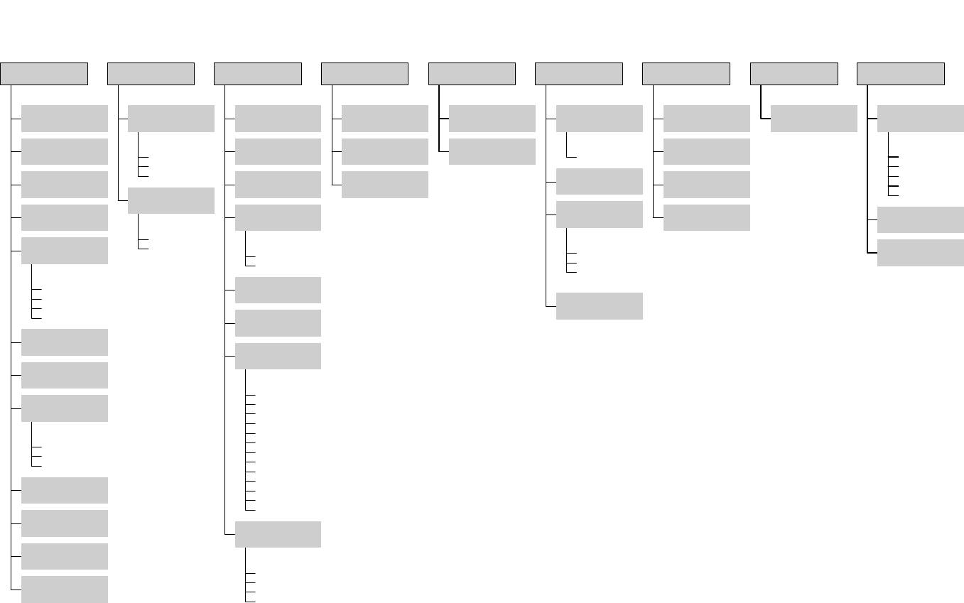
File
Trends
Alarm Log
Data Log
View
Datalogger
SPC
Activate
Log
Display Layout
(data & language)
Conveyor Calibration
(belt or rail encoder)
Alarms
(set alarms & levels)
Weekly Timer
Special Event Calendar
Auto Start/Stop
(set times)
Lubrication
(configure)
Communications
(baud rate & port)
Atmosphere
Analog Wire Map
Auto Rail
Basics
Board Track, Rt-Lft
Conveyor
Controlled Cooling
Digital Wire Map- Out-In
Heater Trend
Heater Tune
Miscelleanous
Transport
Oven Sections
Configure Oven
( type & options)
Burn-in Oven
Process Setup
Thermal Profile
Controlled Cooling Test
Startup
Setup
Run Profiler
KIC Profiler
ECD Profiler
Profiler
Reset Alarms
Reset E-Stop
Reset
Force Outputs
Service Mode
Log Communication
Digital Inputs
Digital Outputs
Anafaze Dipswitch
Settings
I/O
Anafaze Debug
Information
Debug
Message
Calculator
Set Time & Date
Add / View
Printers
Tools
TCP / IP LINK
Host
Site Prep & Installation
Operation, Process & Maint.
TroubleShooting & Service
Operator's Manual
Drawings & Data
MANUALS
How Do I ...
About
Help
Oven Control Program
Version 7.00.00.00
Nov, 2000
VITRONICS REFLOW SOLDERING SYSTEMS
EM 02502-G 15-Nov-00 (c) PAGE Operator’s Manual
8
.
OPERATING SCREEN, MENUS, DIALOGUE BOXES, & SYMBOLS
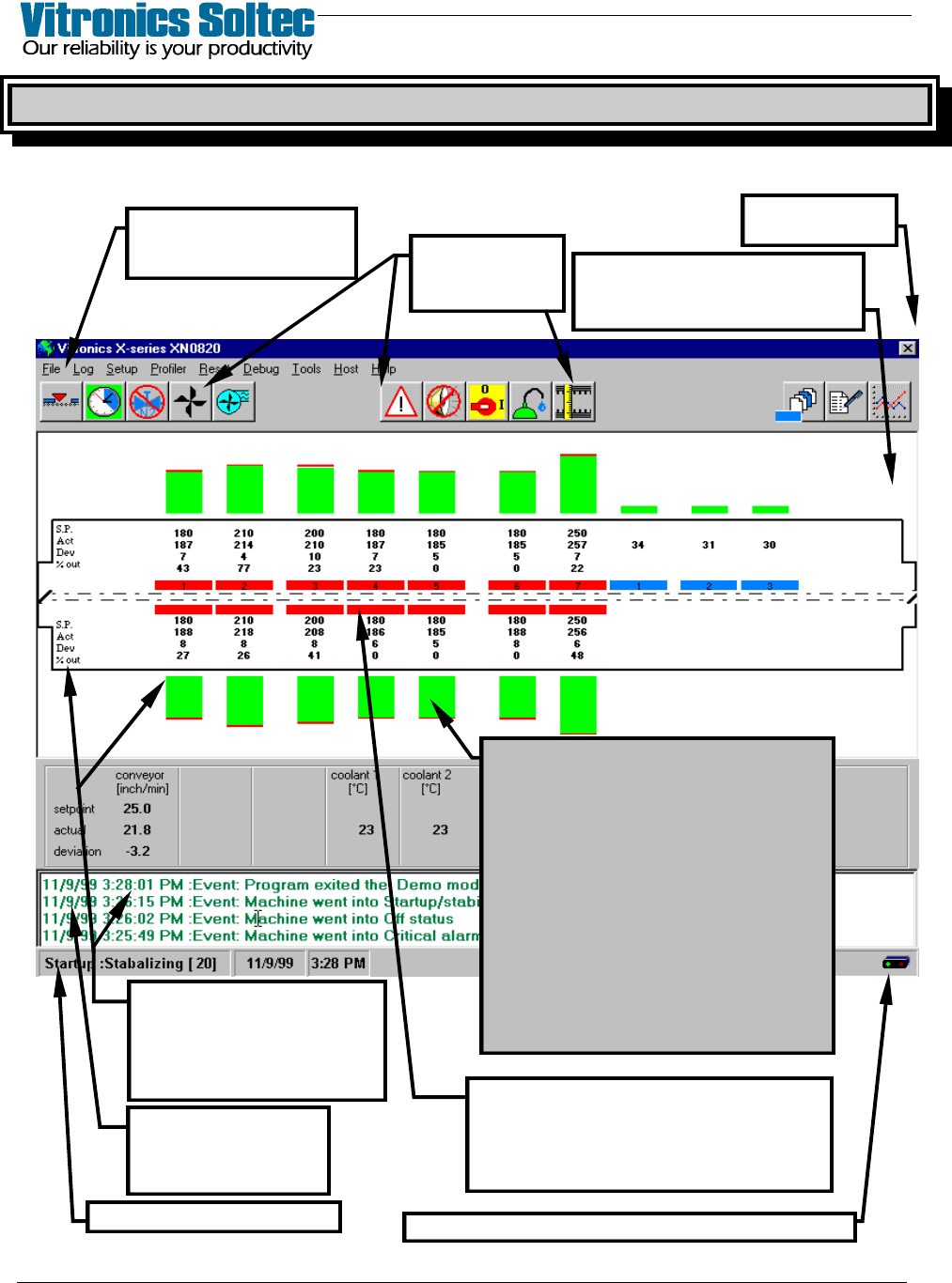
The operating screen is shown here with an XPM-Series XN0820 Oven in Operation.
(Other Ovens with various configurations will be similar, but NOT identical)
PULL-DOWN MENU
(Refer To Menu Diagram
on Opposite Page
SCREEN ICONS
(Descriptions On
Following Pages)
SELECT “X” TO
EXIT PROGRAM
STATUS BAR (See Next Page)
EVENT & ALARM LOG
- Last 4 Shown -
(Double-click to see
complete list)
SHOWN : Setpoints (S.P.)
Measured Value (M.V.)
Deviation (Dev)
% Out (Output)
(Change Setpoints In Pull-Down
Menu)
THE DISPLAY REPRESENTS THE ACTUAL
ARRANGEMENT OF HEATING AND COOLING
CELLS IN THE OVEN.
The Cell Temperature Graphs Are Shown With
Green, Blue, Red and Yellow To Represent The
Measured Temperature Values (M.V.) In
Relation To Actual Setpoints (S.P.)
The color of the Bar Graphs indicates status:
GREEN = PROCESS READY
BLUE = TEMP BELOW SETPOINT
RED = TEMP ABOVE SETPOINT
YELLOW = STABILIZING OR
NOT PROCESS READY
(On ovens with the “Board Tracking Option”,
The Product Will Be Shown Traveling Along The
Conveyor through the Oven)
Blinks red/green when communicating with oven controls
The cell function is indicated by the colors:
LIGHT BLUE = CONTROLLED COOLING
BLUE = COOLING CELLS
RED = HEATING CELLS
GRAY = OFF
SELECT “SETUP”, and “DISPLAY
LAYOUT” TO SET “RED” SCREEN
BACKGROUND WHEN ALARMS
OCCUR
VITRONICS REFLOW SOLDERING SYSTEMS
EM 02502-G 15-Nov-00 (c) PAGE Operator’s Manual
9
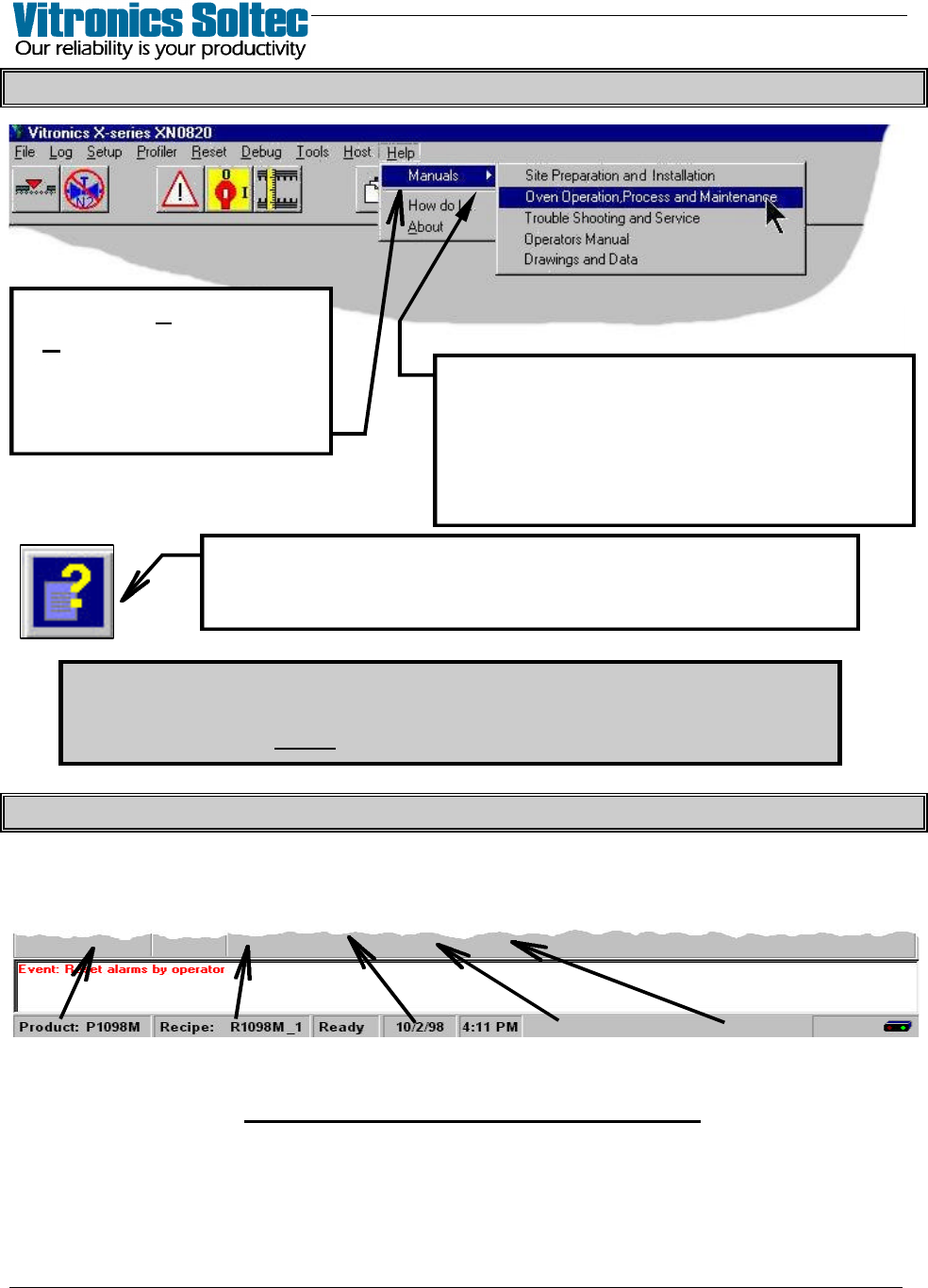
PULL-DOWN MENU ( and getting “Help” )
The password requirements for Menu Items can be turned on/off…
Select: “Files”, then “Access Control”
(A password is always required to change any password requirement)
OVEN STATUS BAR (At Bottom Of Screen)
Active Product, Active Recipe, Oven Status, Today’s Date, Present Time
(click on the items displayed in the Status Bar to Edit them)
OVEN STATUS BAR INFORMATION
When an Item in the Pull-Down Menu is
chosen, more selections are presented.
The small arrow-head after a selection
indicates that more choices will be found
in the Menu at the next level down.
Select “Help”, then
“Manuals” to review Oven
Manuals and schematics.
(Pages can be printed if
printer is connected)
Selecting this Symbol will display “Help” about
the topic where the symbol appears.