WPC4 services manual.pdf - 第15页
Replacing Spare Parts Preparations Drive Unit – Lifting Axis Service Manual SIPLACE WPC4 15 3.3 Drive Unit – Lif ting Axis 3.3.1 Prep arations Tools required Water pump pliers Belt tension device [00326 015-0 1] with…
Replacing Spare Parts
Overview of Main Assemblies
14 Service Manual SIPLACE WPC4
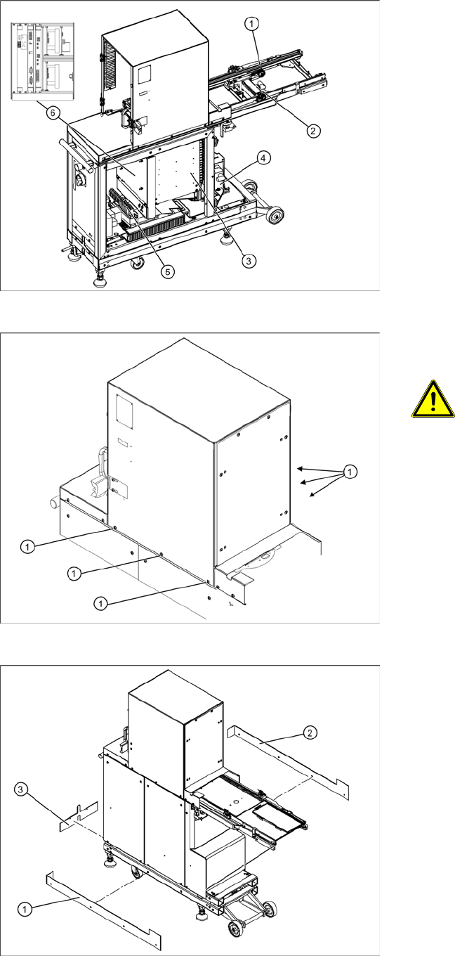
3.2 Overview of Main Assemblies
Overview
1. Feed axis
2. Drive unit – feed axis
3. Lifting axis with tower
4. Drive unit – lifting axis
5. Power supply
6. Control unit (position when fitted)
Screws sealed with locking varnish on
tower
ATTENTION: Do not open screws on
the tower which have been sealed
with locking varnish
The tower is set with these 6 screws (1)
at the factory.
X If you open these screws, the WPC4
must be taken to Siemens AG for
readjustment.
Bottom cover plates
If the WPC4 is configured for high machine
heights, additional cover plates will be attached to
the base.
1. Right-hand cover
2. Left-hand cover
3. Front cover
You may need to remove these covers before
performing service work.
Replacing Spare Parts
Preparations Drive Unit – Lifting Axis
Service Manual SIPLACE WPC4
15
3.3 Drive Unit – Lifting Axis
3.3.1 Preparations
Tools required
Water pump pliers
Belt tension device [00326015-01] with instruction guide
Standard tool with set of Allen wrenches
Required preparations
X Move the tower into the refill position.
X Remove all waffle pack tray carriers (WPTCs) from the tower.
X Move the tower downwards.
SITEST => menu
Functions
=> button
Transport position
.
X Switch the WPC4 off at the main switch.
X Unplug from the power supply and secure the WPC4 to prevent unauthorized reactivation. Refer to
the WPC4 operating manual for details.
X Undock the WPC4 from the SIPLACE machine and move it to a suitable position for service work.
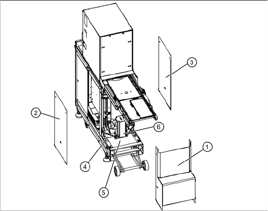
The drive motor (6) of the lifting axis is located
behind the front cover (1). If the drive motor is
disconnected from the power supply, the drive is
fixed with a brake.
X Remove the front cover (1).
X Remove the two side covers (2) + (3).
X Loosen the 4 fastening screws in each case
and remove the two bottom safety covers (4) +
(5). The rear cover plate can be pulled out
towards the front.
Replacing Spare Parts
Drive Unit – Lifting Axis Replacing the Lifting Axis Drive Motor [03047846-xx]
16 Service Manual SIPLACE WPC4
3.3.2 Replacing the Lifting Axis Drive Motor [03047846-xx]
Removal
The drive motor (3) of the lifting axis is located
behind the front cover. If the drive motor is
disconnected from the power supply, the drive is
fixed with a brake.
WARNING: Do not move the motor
against the brake.
Do not move the lifting axis motor shaft
against the brake. This could impair the
braking function or damage the brake.
X
X Unscrew the electrical connections (1) + (2).
X1 orange cable = power cable
X2 green cable = control cable
NOTE: Screw joints difficult to
loosen
Each screw joint has an O-ring seal.
This can make opening the screw joint
difficult.
X Use a pair of water pump pliers to
help you unscrew the connection.
X Make sure that the O-rings do not fall
out of the screw joint and that they
are not damaged.
X When refitting, grease the thread
and the O-rings with a little Vaseline.
X Loosen the two motor support fastening
screws (4) sealed with locking varnish.