WPC4 services manual.pdf - 第17页
Replacing Spare Parts Replacing the Lifting Axis Drive Moto r [03047846-xx] Drive Unit – Lifting Axis Service Manual SIPLACE WPC4 17 1. Lifting axis drive motor 2. 2 x motor s upport fast ening screw s with drive motor 3…
Replacing Spare Parts
Drive Unit – Lifting Axis Replacing the Lifting Axis Drive Motor [03047846-xx]
16 Service Manual SIPLACE WPC4
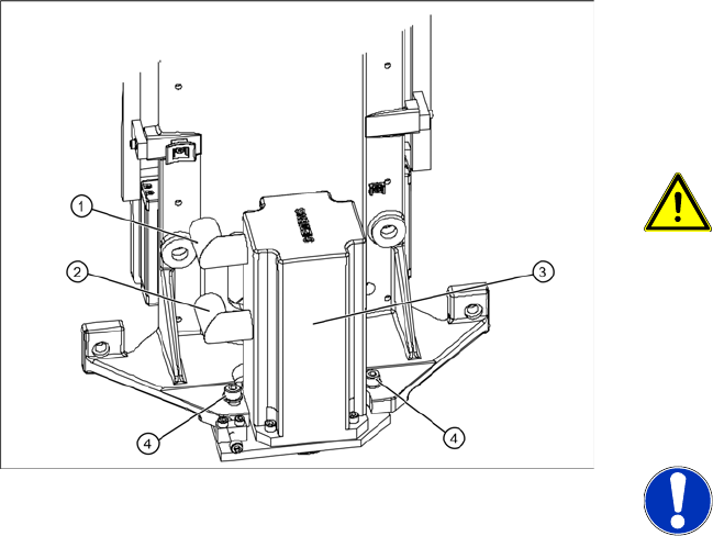
3.3.2 Replacing the Lifting Axis Drive Motor [03047846-xx]
Removal
The drive motor (3) of the lifting axis is located
behind the front cover. If the drive motor is
disconnected from the power supply, the drive is
fixed with a brake.
WARNING: Do not move the motor
against the brake.
Do not move the lifting axis motor shaft
against the brake. This could impair the
braking function or damage the brake.
X
X Unscrew the electrical connections (1) + (2).
X1 orange cable = power cable
X2 green cable = control cable
NOTE: Screw joints difficult to
loosen
Each screw joint has an O-ring seal.
This can make opening the screw joint
difficult.
X Use a pair of water pump pliers to
help you unscrew the connection.
X Make sure that the O-rings do not fall
out of the screw joint and that they
are not damaged.
X When refitting, grease the thread
and the O-rings with a little Vaseline.
X Loosen the two motor support fastening
screws (4) sealed with locking varnish.
Replacing Spare Parts
Replacing the Lifting Axis Drive Motor [03047846-xx] Drive Unit – Lifting Axis
Service Manual SIPLACE WPC4
17
1. Lifting axis drive motor
2. 2 x motor support fastening screws with drive
motor
3. Drive toothed belt
4. 4 x drive motor fastening screws
5. Tensioning screw
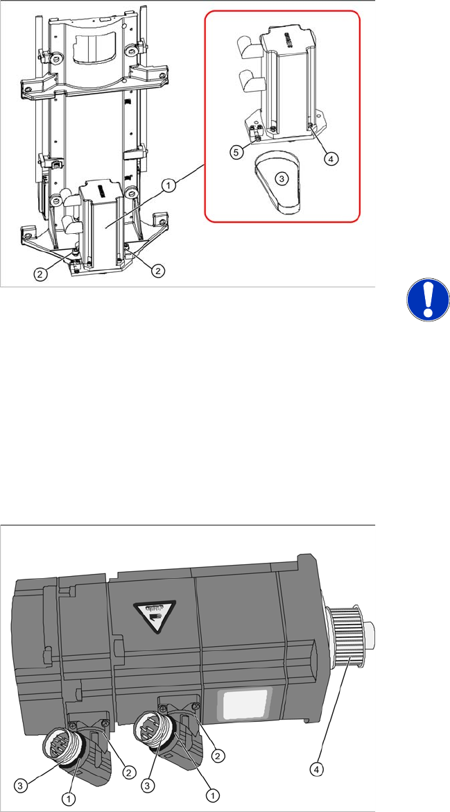
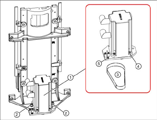
X Loosen (do not remove) the tensioning screw
(5) on the tensioning device. This relaxes the
drive toothed belt.
X Loosen and remove the 2 fastening screws (2)
and then remove the drive motor with motor
support. Make sure that the drive toothed belt
is not buckled or damaged.
NOTE: Tower moves down
The tower moves down about 1 mm, to
the bottom, red bumper.
X Remove the toothed belt.
X Mark the installation position of the drive motor
on the motor support.
X Loosen the 4 drive motor fastening screws (4)
on the motor support.
X Fit the new drive motor with the 4 fastening
screws (4) to the motor support. Observe the
original installation position.
Overview of motor
1. O-ring
2. Rotary connection
3. Thread
4. Motor pinion
X The motor connections can be rotated by
hand. Rotate the connections to the position
the motor was installed in before.
X Grease the thread (3) and the O-rings (1) with
a little Vaseline.
Replacing Spare Parts
Drive Unit – Lifting Axis Replacing the Lifting Axis Drive Motor [03047846-xx]
18 Service Manual SIPLACE WPC4
Installation
X Loosely fix the motor support and drive motor
into the installation position, with the 2
fastening screws (2).
X Reconnect the electrical connections with the
motor. When fitting, note that there is an anti-
twist lock (notch) present. Tighten the
connection appropriately.
X Run the drive toothed belt around the motor
pinion and the spindle toothed wheel and
tension (pretension) the toothed belt at the slot
provided, with the help of the motor support.
X Set the final belt tension. To do this, tension
the drive toothed belt at the tensioning device,
with the help of the tensioning screw (5). This
moves the motor support accordingly in the
slots.
Setting: set belt tension to
235 Hz.+/- 10 Hz.
X Tighten the 2 fastening screws (2) on the
motor support, check the belt tension and
adjust where necessary.
X Seal the 2 fastening screws (2) with locking
varnish.
X Calibrate the lifting axis.