WPC4 services manual.pdf - 第52页
Replacing Spare Parts Limit Switches, Sensors and Light Barr iers Replacing the F eed Axis Limit Switch on Tower Side [03047276-xx] 52 Service Manual SIPLACE WPC4 X If necessary, correct the mechan ical position of the l…
Replacing Spare Parts
Replacing the Feed Axis Limit Switch on Tower Side [03047276-xx] Limit Switches, Sensors and Light Barriers
Service Manual SIPLACE WPC4
51
3.6.7 Replacing the Feed Axis Limit Switch on Tower Side [03047276-xx]
Settings
X Check the function and correct position of the limit switch. The limit switch must switch when the
edge of the catch (4) moves over the switch (end position).
X To do this, open the SITEST main view and select the function=>
SITEST Settings
.
X In the input area
Axis,
select the button
Feed axis
.
X In the input area
Travel range
select the button
Limit switch +
.
The feed axis will be moved so that the catch moves over the limit switch. The limit (end position)
will be calculated.
In the SITEST main view, function=>
SITEST inputs/outputs 1,
the display
Feed axis limit switch
on tower side
will be activated.
A dialog box will open and the calculated value will be shown. The permissible limits (minimum/
maximum position) will also be shown. The end position must be within these limits.
X Check the permissible limits against the value actually measured.
Spare part
Limit switch, feed axis, operator side
[03047276-01]
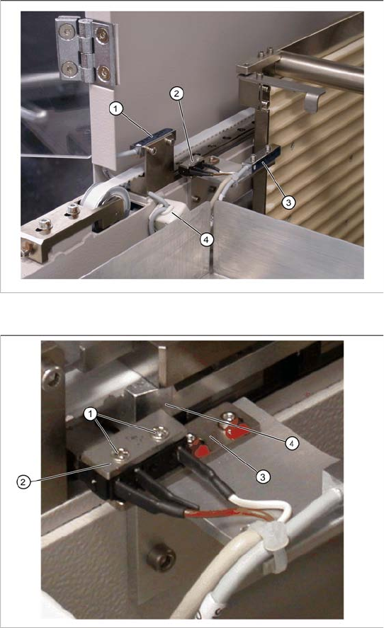
Overview
1. Reference sensor, feed axis
2. Feed axis limit switch on tower side
3. WPTC lock sensor closed
4. Ferrite core for EMC interference suppression
at feed axis reference sensor
X Mark the exact position of the limit switch on
the mounting bracket (3).
X Loosen the two fastening screws (1) on the
limit switch.
X Remove the fixture plate (2).
X Loosen the cable clamps and remove the
cable ties.
X Unthread the connection cable as far as the
control unit back plane and unplug it from the
terminal strip.
X Fit the new limit switch with fixture plate (2) at
the marked installation position.
X Align the limit switch parallel to the mounting
bracket .
X Restore the electrical connection and fix the
connection cable into place with new cable
ties.
Replacing Spare Parts
Limit Switches, Sensors and Light Barriers Replacing the Feed Axis Limit Switch on Tower Side [03047276-xx]
52 Service Manual SIPLACE WPC4
X If necessary, correct the mechanical position of the limit switch and repeat the measurement
procedure.
X If the value is within the permissible limits, save the data by clicking on
Accept
.
X Seal the two mounting bracket fastening screws with locking varnish.
Replacing Spare Parts
Replacing the Collision Light Barriers [03047281-xx] Limit Switches, Sensors and Light Barriers
Service Manual SIPLACE WPC4
53
3.6.8 Replacing the Collision Light Barriers [03047281-xx]
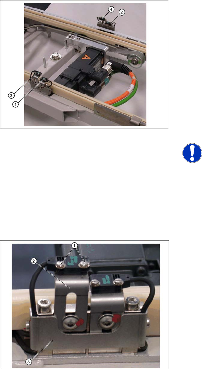
Overview
1. Collision light barrier for normal components
(receiver) with LED
2. Collision light barrier for normal components
(transmitter)
3. Collision light barrier for high components
(transmitter)
4. Collision light barrier for high components
(receiver) with LED
Spare parts
Collision LB for normal components
[03047281-01]
Collision LB for high components [03047282-
01]
NOTE: Transmitter and receiver
together as one spare part
The transmitter and receiver of the
relevant collision light barrier are
stocked as one spare part with one part
number.
X Depending on the error occurring,
you may need to replace the
transmitter and receiver together.
X Loosen the two fastening screws (1) for the
relevant sensor (transmitter or receiver) on the
mounting bracket (2).
X Loosen the two screws holding the cable
fixtures (3).
X You need to remove the plastic guidance on
the right-hand side, so that you can unthread
the plug or light barrier.
X Loosen the cable clamps and remove the
cable ties.
X Unthread the connection cable as far as the
control unit back plane and unplug it from the
terminal strip.
X Fit the sensor on the mounting bracket (2).
X Align the sensor parallel to the mounting
bracket (3).
X Restore the electrical connection and fix the
connection cable into place.
Settings
Set the collision light barriers. See Section 3.6.8.1
Einstellung der Crashlichtschranken [J54].