WPC4 services manual.pdf - 第29页
Replacing Spare Parts Control Unit Control Unit and Power Supply Unit Service Manual SIPLACE WPC4 29 3.5.1 Control Unit 3.5.1.1 Instructions for W orking with Control Unit s View of back - details 1. Connections for limi…
Replacing Spare Parts
Control Unit and Power Supply Unit Setting the Feed Axis Belt Tension
28 Service Manual SIPLACE WPC4
3.5 Control Unit and Power Supply Unit
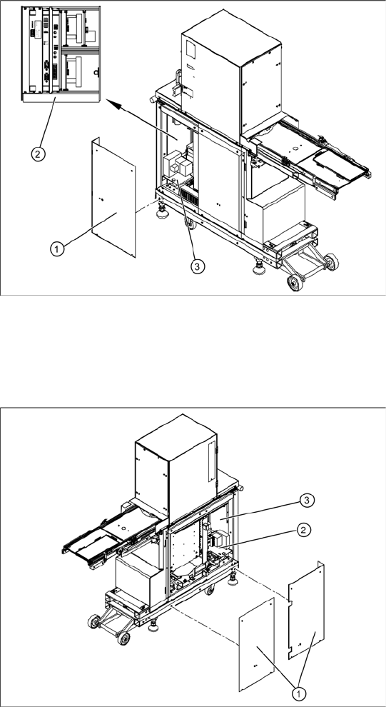
Front side
X Remove the 4 screws (1) fastening the side
covers. Underneath, you will see the front end
of the control unit (2) and the front end of the
power supply unit (3).
The front end of the control unit contains the
Servo and axis controller boards
Ballast circuit
Power supply board
Controller board
The front end or installation plate of the power
supply unit contains the
Protective contactor combination SSK – K1
Contactors K2/K3
Primary and secondary transformer fuses
Back
X Remove the 8 screws (1) fastening the two
side covers. Underneath, you will see the back
of the control unit (3) and the back of the power
supply unit (2).
The back of the control unit contains the terminal
strips and the plug-and-socket connections,
the limit switches, sensors and light barriers
The drive motors (lifting and feed axis)
The fan connection etc.
The back part or installation plate of the power
supply contains the
Inrush current limitation board A1 with K4
Line filter for 3-phase system
Rectifier bridge
Transformer
Replacing Spare Parts
Control Unit Control Unit and Power Supply Unit
Service Manual SIPLACE WPC4
29
3.5.1 Control Unit
3.5.1.1 Instructions for Working with Control Units
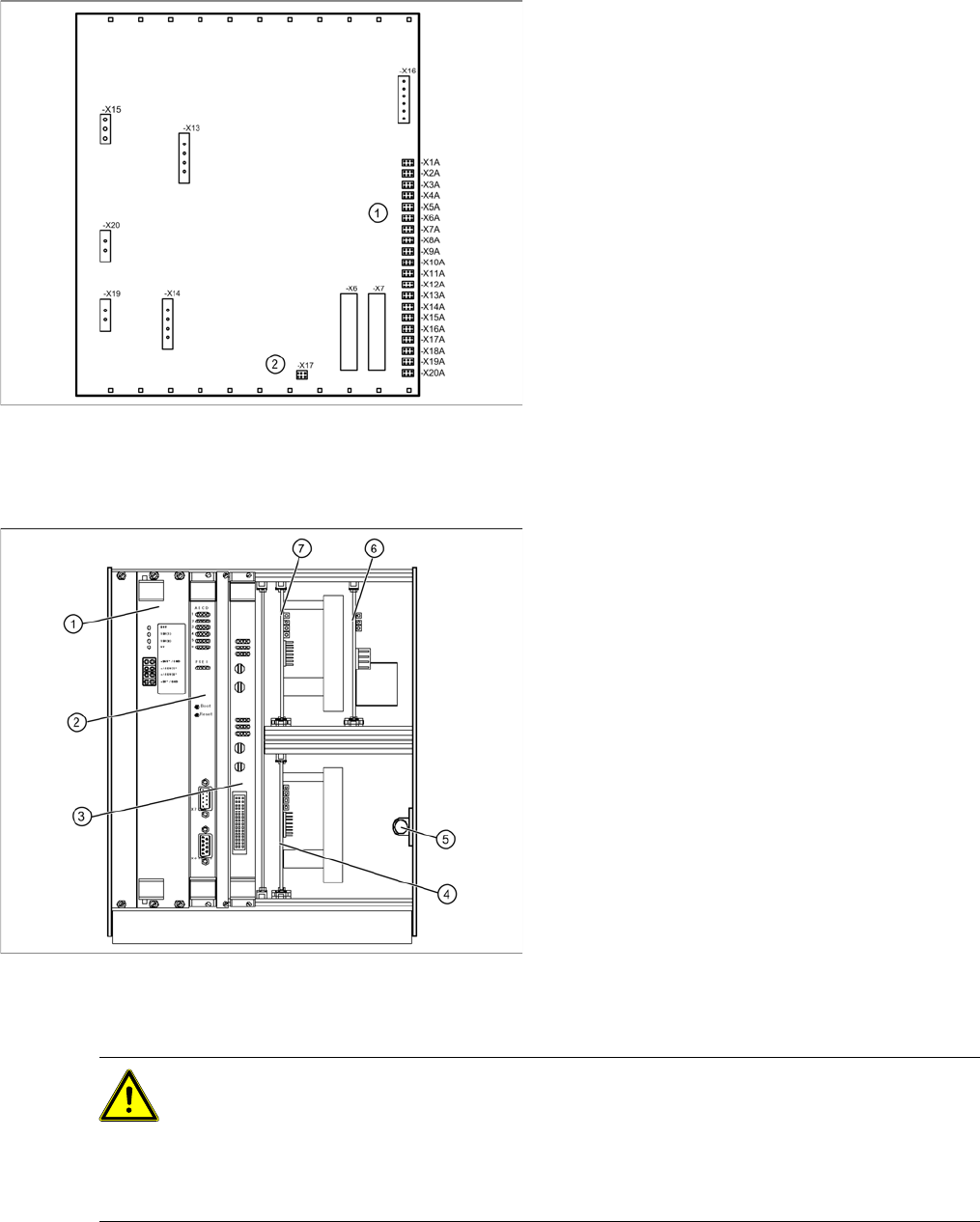
View of back - details
1. Connections for limit switches, sensors and
light barriers
2. Fan connection
X For connection details and complete circuit
diagrams, please refer to the following
documentation:
SIPLACE D1 detailed circuit diagrams
[00194841-xx] German
SIPLACE D1 detailed circuit diagrams
[00194841-xx] English
Overview
1. Supply board
2. Controller board
3. Axis controller board KSP A364 analog
4. Servo amplifier for lifting axis (10A)
5. Braking resistor for lifting axis
6. Ballast circuit
7. Servo amplifier for feed axis (3A)
CAUTION: Observe the ESD regulations!
When handling control unit assemblies, observe the ESD regulations for your own safety and
the safety of the machine:
X When removing or installing individual assemblies, always wear the ESD wristband, to
prevent damage to the electronics system.
X Also observe the ESD regulations specified SIPLACE D1/D2 machine operating manuals.

Replacing Spare Parts
Control Unit and Power Supply Unit Control Unit
30 Service Manual SIPLACE WPC4
3.5.1.2 Replacing the Power Supply Board [03047225-xx]
Spare part
WPC power supply board [03047225-02]
Removal/installation
X Wear the ESD wristband.
X Loosen the 4 screws fastening the front plate of the power supply board.
X Carefully pull the power supply board (see Section 3.5.1 Control Unit [J29]) out of the control unit.
X Carefully insert the new power supply board.
X Make sure that the power supply board engages properly.
X Tighten the 4 screws fastening the front plate of the power supply board.
Settings
There are no settings required.
3.5.1.3 Replacing the Controller Board [03047223-xx]
Spare part
WPC controller board [03047223-02]
Removal/installation
X Make a backup copy of the machine data, if this is still possible
(*.MA
). See Section 4.3.2 Saving
the Machine Data [J66].
X Wear the ESD wristband.
X Unplug the CAN bus cable from the front of the controller board.
X Loosen the 2 screws fastening the front plate of the controller board.
X Carefully pull the controller board (see Section 3.5.1 Control Unit [J29]) out of the control unit.
X Carefully insert the new controller board.
X Make sure that the controller board engages properly.
X Tighten the 4 screws fastening the front plate of the controller board.
X Plug the CAN bus cable back into the front of the controller board.
Settings
X Perform a firmware download (BIOS and application) for the controller board.
To do this, open the SITEST main view and select the function=>
Download
=> tab
WPC
. For
further information, refer to the SITEST manual for placement machines.
X Restore the
*.MA data
for which you made a backup copy. See Section 4.3.3 Restoring Machine
Data [J66].
NOTE: Check the power supply board voltages.
The green LEDs on the power supply board only show whether voltage is present or not
(function monitoring). They do not show whether this voltage is correct.
X Use a digital multimeter to measure the voltages at the respective pins on the front plate of
the power supply board.
NOTE: Backup battery
A backup battery is located on the controller board.
X Replace this battery if you are shown the error message "17802 WPC: Voltage of back-up
battery is too low“.
NOTE: Calibration
If you are able to restore a current MA file, you do not need to recalibrate the WPC4.
If you are unable to restore a current MA file, you will need to recalibrate the WPC4.