WPC4 services manual.pdf - 第48页
Replacing Spare Parts Limit Switches, Sensors and Light Barriers Replacing the Referenc e Sensor, Feed Axis [03047273-xx] 48 Service Manual SIPLACE WPC4 Settings X Check the function and correct position of the refe renc…
Replacing Spare Parts
Replacing the Reference Sensor, Feed Axis [03047273-xx] Limit Switches, Sensors and Light Barriers
Service Manual SIPLACE WPC4
47
3.6.5 Replacing the Reference Sensor, Feed Axis [03047273-xx]
Installation
X Loosely screw the reference sensor onto the mounting bracket.
X Note the installation position. The sensor surface must point downwards.
X Run the connection cable through the feed-through hole in the mounting bracket. This cable feed-
through hole serves as a strain relief for the connection cable.
X Fit the mounting bracket with the two fastening screws.
X Leave a sufficiently large loop of cable, so that you can fit the cable in the ferrite core.
X Align the reference sensor parallel to the top edge of the mounting bracket and tighten the two
fastening screws on the reference sensor.
X Restore the electrical connection and fix the connection cable into place.
Spare part
Reference point proximity switch for feed axis
[03047273-01]
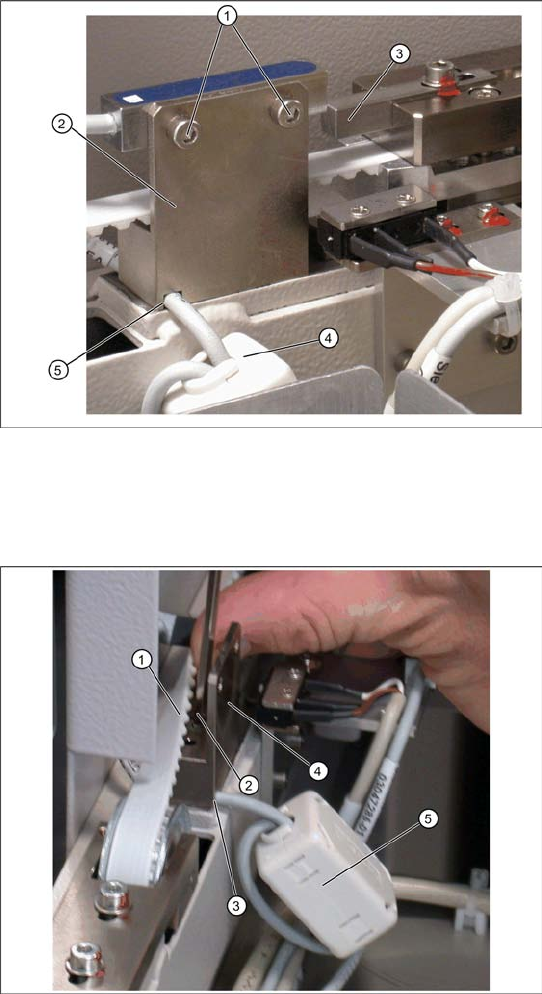
Overview
1. Reference sensor fastening screws
2. Mounting bracket
3. Actuator
4. Ferrite core for EMC interference suppression
at feed axis reference sensor
5. Cable feed-through hole on mounting bracket
Removal
X Loosen the two screws (1) fastening the
proximity switch mounting bracket (3).
X In order to remove the cable at the cable feed-
through hole (5), you need to also remove the
mounting bracket (2).
X Loosen the two screws (1) sealed with locking
varnish, which fasten the reference sensor
mounting bracket.
X To do this, you need to push the feed axis
toothed belt (2) a little to the side, so that you
can reach the two fastening screws (1) . Make
sure that the toothed belt is not buckled or
damaged.
X Remove the connection cable at the cable
feed-through hole (3) on the mounting bracket
(4).
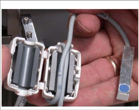
X Open the ferrite core (5) at the fixtures
provided, with the help of a screwdriver.
X Unthread the cable clamp and remove the
ferrite core. Keep these in a safe place for later
installation.
X Unthread the connection cable as far as the
control unit back plane and unplug it from the
terminal strip.
Replacing Spare Parts
Limit Switches, Sensors and Light Barriers Replacing the Reference Sensor, Feed Axis [03047273-xx]
48 Service Manual SIPLACE WPC4
Settings
X Check the function and correct position of the reference sensor. The sensor must trigger when the
catch actuator is just below the sensor. (Reference point).
X To do this, open the SITEST main view and select the function=>
SITEST Settings
.
X In the input area
Axis,
select the button
Feed axis
.
X In the input area
Travel range
select the button
Reference bero
.
The feed axis will be moved so that the catch actuator switches the reference sensor.The reference
point will be calculated.
In the SITEST main view, function=>
SITEST inputs/outputs 1,
the display
Reference sensor,
feed axis
will be activated.
A dialog box will open and the calculated reference point will be shown.The permissible limits
(minimum/maximum position) will also be shown.The reference point must be within these limits.
X Check the permissible limits against the value actually measured.
X If necessary, correct the mechanical position of the reference sensor and repeat the measurement
procedure.
X If the value is within the permissible limits, save the data by clicking on
Accept
.
X Seal the two mounting bracket fastening screws with locking varnish.
X Insert the connection cable into the ferrite core
(one loop).
X Press the two halves together so that the
fixture engages.
Replacing Spare Parts
Replacing the Reference Sensor, Feed Axis [03047273-xx] Limit Switches, Sensors and Light Barriers
Service Manual SIPLACE WPC4
49
See also:
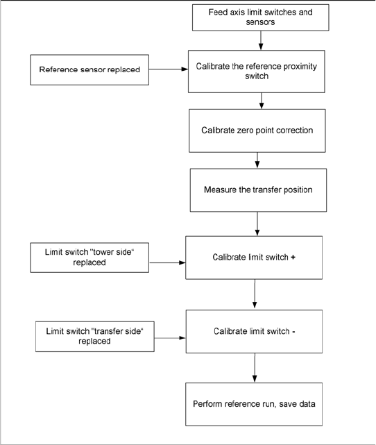
J 4.2.5 Measuring the Transfer Position [J65]
X Perform the necessary calibrations in SITEST,
according to the flow chart. Observe the
correct order.