WPC4 services manual.pdf - 第37页
Replacing Spare Parts Power Supply Unit Control Unit and Power Supply Unit Service Manual SIPLACE WPC4 37 3.5.2.1 Replacing the Protective Cont actor Co mbination (SSK) [00372649-xx] 3.5.2.2 Replacing the Inrush current …
Replacing Spare Parts
Control Unit and Power Supply Unit Power Supply Unit
36 Service Manual SIPLACE WPC4
Settings
X Check the flow of air from the fan. The fan takes in air from below and blows it into the inside of the
control unit.
3.5.2 Power Supply Unit
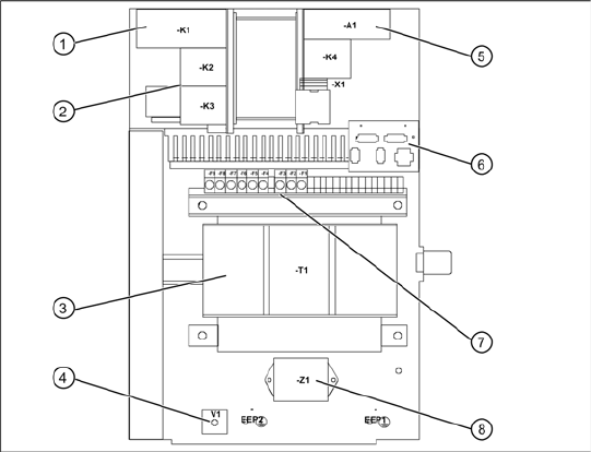
Overview of power supply - view from
above
1. Protective contactor combination SSK
2. Contactors K2/K3
3. Transformer
4. Rectifier bridge
5. Inrush current limitation board A1 with K4
6. Plug/interface to front (emergency stop/main
switch etc.)
7. Primary and secondary transformer fuses
8. Line filter for 3-phase system
X For connection details and complete circuit
diagrams, please refer to the following
documentation:
SIPLACE D1 detailed circuit diagrams
[00194841-xx] German
SIPLACE D1 detailed circuit diagrams
[00194841-xx] English
Replacing Spare Parts
Power Supply Unit Control Unit and Power Supply Unit
Service Manual SIPLACE WPC4
37
3.5.2.1 Replacing the Protective Contactor Combination (SSK) [00372649-xx]
3.5.2.2 Replacing the Inrush current Limitation Board [03047752-xx]
The inrush current limitation board is located at the back of the electrical unit (see Section 3.5.2 Power
Supply Unit [J36]).
Spare part
Inrush current limitation board WPC4 [03047752-01]
Removal/installation
X Label all connections for easier installation later.
X Unplug all connections from the inrush current limitation board.
X Lever the inrush current limitation board off the mounting rail.
X Connect the new inrush current limitation board to the mounting rail and restore the electrical
connections.
Settings
There are no settings required.
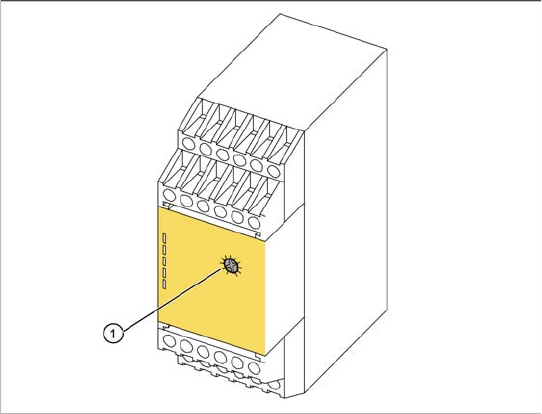
The protective contactor combination (SSK) is
located at the front of the electrical unit (see
Section 3.5.2 Power Supply Unit [J36]).
1. Setting screw
Spare part
Protective contactor combination (SSK)
3TK2828-1BB41 [00372649-01]
Removal/installation
X Label all connections for easier installation
later.
X Unplug all connections from the protective
contactor combination.
X Lever the protective contactor combination off
the mounting rail.
X Connect the new protective contactor
combination to the mounting rail and restore
the electrical connections.
Settings
X Adjust the setting screw (1) to a value of 0.5
(seconds). If the value is set too high, an error
message will be issued.
X Seal the setting screw with locking varnish.
Replacing Spare Parts
Control Unit and Power Supply Unit Power Supply Unit
38 Service Manual SIPLACE WPC4
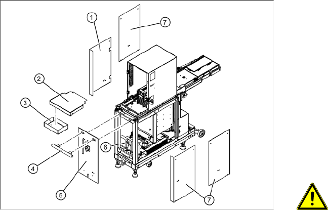
3.5.2.3 Removing the Front Cover Plate with Main Switch and the Emergency Stop Button
X Remove the side cover plate (1), in order to
access the power supply connections. If
necessary (depends on the service work to be
performed), you can also remove other side
covers (7).
X Loosen the 4 screws fastening the cover (2)
and remove this from the WPC4.
X Loosen the 2 screws fastening the service box
(3) and remove this from the WPC4. The
fastening screws on the handle (4) can now be
loosened from inside.
X Loosen the 2 screws on the inside of the
handle (4) and remove the handle.
WARNING: Voltage at cable to main
switch
When the WPC4 power cable is
connected and the main switch has
been turned off, voltage is still present
at the cable to the main switch, at the
mains filter and at the terminals to the
main switch.
X Disconnect the WPC4 from the
power supply.
X Check whether all cables are labeled(X1h to
X5h).
X Make sure that you will be able to correctly
assign all cables and plugs again. Where
necessary, label cables, plugs and
connections for easier reconnection later.
X Disconnect the cables (X1h to X5h) from the
installation plate of the power supply unit (6).
X Loosen the 4 fastening screws on the front
plate cover (5).
X The main switch and the emergency stop
button are now accessible for service
purposes.
X Loosen the ground terminal on the front plate
cover, if you need to remove the complete
front plate cover.