TM4230.SmartRecognition.pdf - 第11页
S M T S o f t w a r e E n g i n e e r i n g G r o u p I M O p e r a t i o n s Y A M A H A M O T O R C O . , L T D . MDOC-SOFT50185 7) Set the center of the pa rts. W hen you go to the [Create Model] screen…

SMTSoftwareEngineeringGroup
IMOperationsYAMAHAMOTORCO.,LTD.
MDOC-SOFT50185
④ Edge Threshold(Slide bar button)
Allows you to change the edge threshold value ±1 by one-click.
⑤ Manual Compress
When [Manual] is checked, [⑥Manual Compress Level] is enabled.
⑥ Manual Compress Level
Allows you to select a manual compressing level.
You can select a level from 1/1 to 1/10.
Compressing level decided automatically is displayed here in gray.
⑦ Erase edge manually
When [Erase edge manually] is checked, ⑧ to ⑪ are enabled.
⑧ Erase Edge(Point)
Allows you to change how to erase edges to the Point mode.
The mouse cursor on the vision window turns to an eraser, and you can erase
any edge as you like by dragging the mouse.
⑨ Erase Edge(Rectangle)
Allows you to change how to erase edges to the Rectangle mode.
You can select an area by dragging the mouse, and erase edges in the area at
once.
⑩ Erase Edge(Undo)
Restores erased edges to the previous status.
If the edges have been erased in the point mode, they are not restored
point-by-point, but restored by each dragging mouse action.
⑪ Erase Edge(Undo All)
Restores all erased edges to the original status.
※ [Attention] Please note that the edge condition will be initialized, if you go back to the
[Get Image] screen from the [Create Model] screen
※ [Attention] Please note that the edge condition will be initialized, if you execute Manual
Compress after erasing edges.
SMTSoftwareEngineeringGroup
IMOperationsYAMAHAMOTORCO.,LTD.
MDOC-SOFT50185
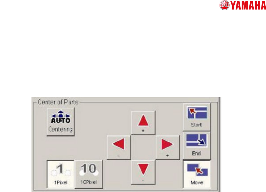
7) Set the center of the parts.
When you go to the [Create Model] screen and parts edges are detected, the edges
are surrounded with a circumscribed square frame of green dots line, and its center is
automatically detected.
However, if you executed [6] Adjust detected edges, the circumscribed frame may
have been changed as well. In that case, you need to set the center again.
To set the center, press the [Centering] button. Also you can set it manually.
① Auto centering
Automatically detects the center of the circumscribed frame on the vision window.
Circumscribed frame : Square surrounding the point of max and min XY
where edges exist.
Center Position : The vertex of divided circumscribed frame in half.
② Manual centering (Select how to move)
Start : Changes to the mode, in which the center of the circumscribed frame is
resized with its lower right portion fixed.
End : Changes to the mode, in which the center of the circumscribed frame is
resized with its upper left portion fixed.
Move : Changes to the mode, in which the whole of the center of the
circumscribed frame is moved.
After you select a mode, press the ④ button to move the frame to the specified
position.
③ Manual centering (Select moving range)
Allows you to select a moving range by one-click of [④Manual centering(Move)] to
resize or move the circumscribed frame.
④ Manual centering(Move)
Resizes or moves the circumscribed frame. It works in the mode you select in [②
Manual(Select how to move)] and [③Manual(Select moving range)].
①
①①
①
②
②②
②
③
③③
③
④
④④
④
SMTSoftwareEngineeringGroup
IMOperationsYAMAHAMOTORCO.,LTD.
MDOC-SOFT50185
8) Move to the Vision Test screen
Press the [Next] button to go to the [Vision Test] screen.
Smart Recognition model data will be created based on the data you created on the
[Create Model] screen.
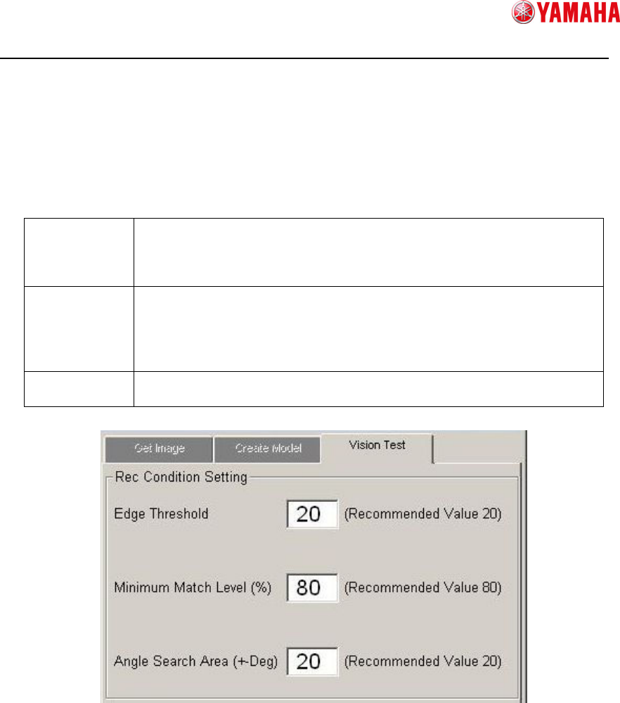
9) Set recognition conditions
Set conditions for Smart Recognition.
Edge
Threshold
If the reflection of the parts is dark, set a threshold value lower than
that you have created on the Create Model screen, which enables to
detect more edges.
It is recommended to set this value “20” or more.
Minimum
Match Level
This is the basis to judge the match level between model data and
recognition image.
If the match level is lower than this value, a recognition error occurs.
If this level is too low, it can cause mis-recognition or mis-judgement.
It is recommended to set this value “80” or more.
Angle Search
Area
Detectable parts angle setting.
It is recommended to set this value within “20” degree.
① Edge Threshold
Input [Edge Threshold].
② Minimum Match Level
Input [Minimum Match Level].
③ Angle Search Area
Input [Angle Search Area].
①
①①
①
②
②②
②
③
③③
③