TM4230.SmartRecognition.pdf - 第5页
S M T S o f t w a r e E n g i n e e r i n g G r o u p I M O p e r a t i o n s Y A M A H A M O T O R C O . , L T D . MDOC-SOFT50185 4.2.2 How to create model dat a Model data for Smart Recognition is create…
SMTSoftwareEngineeringGroup
IMOperationsYAMAHAMOTORCO.,LTD.
MDOC-SOFT50185
4.2. Create model data
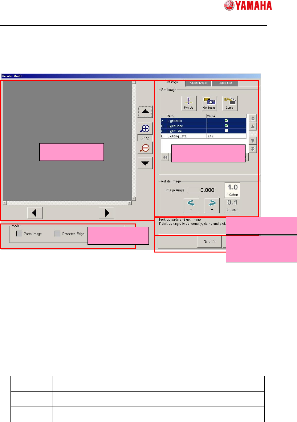
4.2.1 Screen Structure
① Vision Window
Displays vision images such as captured image and edge image.
② Mode
Allows you to select an image type to display on Vision Window.
③ Operation Window
Allows you to operate the model creation process here throughout Capturing Image,
Creating Model, and Vision Test. This screen is displayed in the wizard format.
④ Guide Message
Displays guide messages you need to do next.
⑤ Screen Change Buttons
Next Goes to the next screen.
Back Goes back to the previous screen.
OK Saves the model data you are creating in the parts adjust data and goes
back to the parts adjust screen.
Cancel Cancels all model data you are creating and goes back to the parts
adjust screen.
①
①①
①Vision Window
③
③③
③Operation Window
②
②②
②Mode
④
④④
④Guide Message
⑤
⑤⑤
⑤Screen Change
Button
SMTSoftwareEngineeringGroup
IMOperationsYAMAHAMOTORCO.,LTD.
MDOC-SOFT50185
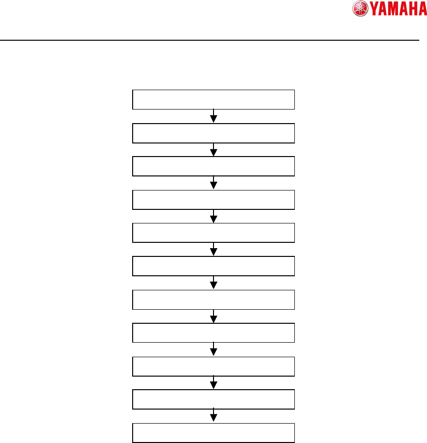
4.2.2 How to create model data
Model data for Smart Recognition is created through the following procedure.
Explains details of each step below.
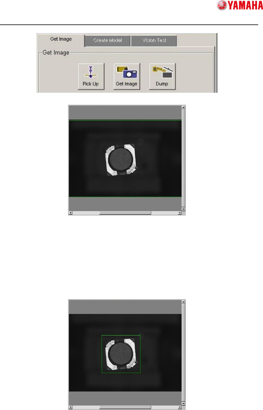
1) Pick up parts
Press the [Pick Up] button on the [Get Image] screen to pick up parts.
In case of the parts already picked up on the head, you can skip this step.
2) Capture an image
Press the [Get Image] button to capture the parts image.
The parts will be recognized by the vision camera and the captured image will be
displayed on the vision window.
In case of the parts picked up out of the center of the nozzle or with too much rotated,
press the [Dump] button and try it again.
1) Pick up parts
2) Capture an Image
3) Specify edge detection frame
4) Correct the image angle
5) Move to the Create Model screen
6) Adjust detected edges
7) Set the center of parts
8) Move to the Vision Test screen
9) Set the recognition condition
10) Vision Test
11) Save model data
SMTSoftwareEngineeringGroup
IMOperationsYAMAHAMOTORCO.,LTD.
MDOC-SOFT50185
3) Specify edge detection frame
To specify an edge detection frame, enclose the parts by dragging the mouse on the
vision window.
Just after the image captured, the outer frame of the image is automatically set as its
edge detection frame. You can go to the next step without adjusting the frame, but in
that case, there is a possibility that something on the white space can be detected
incorrectly as parts edges. Therefore, it is recommended to set edge detection frame
with its absolute minimum margin.