TM4230.SmartRecognition.pdf - 第12页
S M T S o f t w a r e E n g i n e e r i n g G r o u p I M O p e r a t i o n s Y A M A H A M O T O R C O . , L T D . MDOC-SOFT50185 8) Move to t he Vision T est sc reen Press the [Next] button t o go to the…
SMTSoftwareEngineeringGroup
IMOperationsYAMAHAMOTORCO.,LTD.
MDOC-SOFT50185
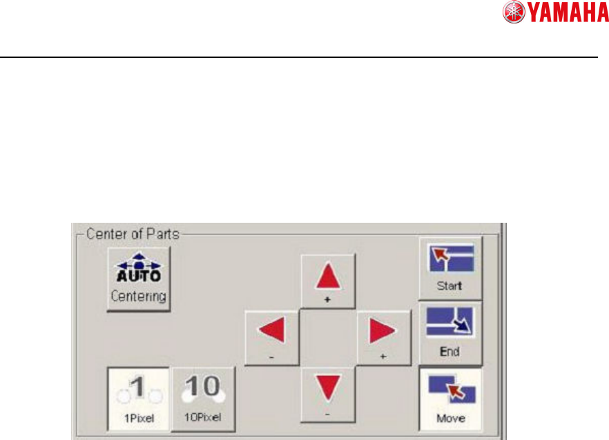
7) Set the center of the parts.
When you go to the [Create Model] screen and parts edges are detected, the edges
are surrounded with a circumscribed square frame of green dots line, and its center is
automatically detected.
However, if you executed [6] Adjust detected edges, the circumscribed frame may
have been changed as well. In that case, you need to set the center again.
To set the center, press the [Centering] button. Also you can set it manually.
① Auto centering
Automatically detects the center of the circumscribed frame on the vision window.
Circumscribed frame : Square surrounding the point of max and min XY
where edges exist.
Center Position : The vertex of divided circumscribed frame in half.
② Manual centering (Select how to move)
Start : Changes to the mode, in which the center of the circumscribed frame is
resized with its lower right portion fixed.
End : Changes to the mode, in which the center of the circumscribed frame is
resized with its upper left portion fixed.
Move : Changes to the mode, in which the whole of the center of the
circumscribed frame is moved.
After you select a mode, press the ④ button to move the frame to the specified
position.
③ Manual centering (Select moving range)
Allows you to select a moving range by one-click of [④Manual centering(Move)] to
resize or move the circumscribed frame.
④ Manual centering(Move)
Resizes or moves the circumscribed frame. It works in the mode you select in [②
Manual(Select how to move)] and [③Manual(Select moving range)].
①
①①
①
②
②②
②
③
③③
③
④
④④
④
SMTSoftwareEngineeringGroup
IMOperationsYAMAHAMOTORCO.,LTD.
MDOC-SOFT50185
8) Move to the Vision Test screen
Press the [Next] button to go to the [Vision Test] screen.
Smart Recognition model data will be created based on the data you created on the
[Create Model] screen.
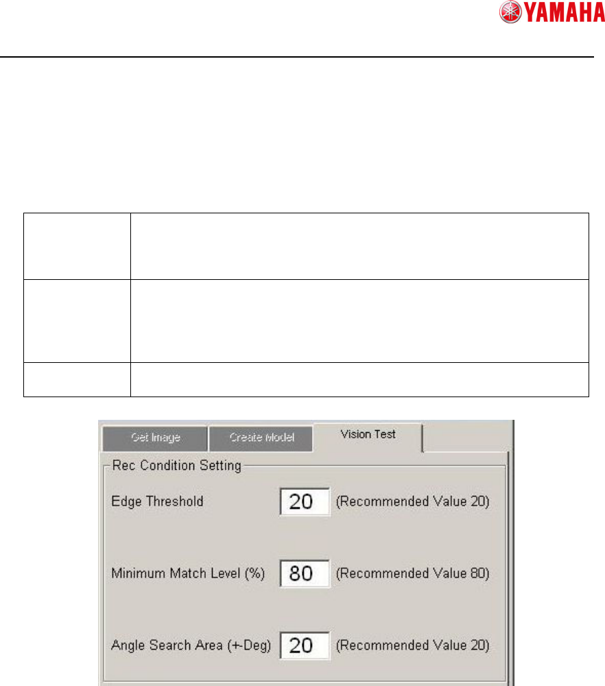
9) Set recognition conditions
Set conditions for Smart Recognition.
Edge
Threshold
If the reflection of the parts is dark, set a threshold value lower than
that you have created on the Create Model screen, which enables to
detect more edges.
It is recommended to set this value “20” or more.
Minimum
Match Level
This is the basis to judge the match level between model data and
recognition image.
If the match level is lower than this value, a recognition error occurs.
If this level is too low, it can cause mis-recognition or mis-judgement.
It is recommended to set this value “80” or more.
Angle Search
Area
Detectable parts angle setting.
It is recommended to set this value within “20” degree.
① Edge Threshold
Input [Edge Threshold].
② Minimum Match Level
Input [Minimum Match Level].
③ Angle Search Area
Input [Angle Search Area].
①
①①
①
②
②②
②
③
③③
③
SMTSoftwareEngineeringGroup
IMOperationsYAMAHAMOTORCO.,LTD.
MDOC-SOFT50185
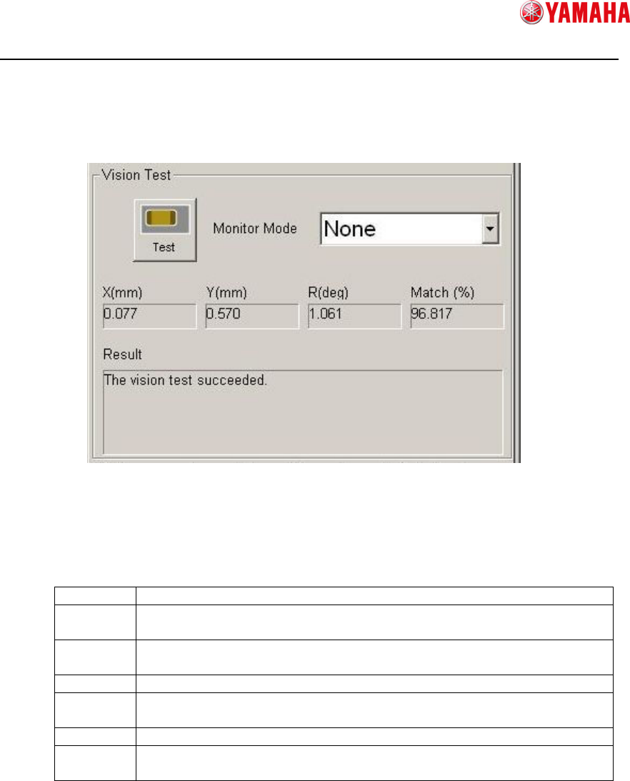
10) Vision test
Executes a vision test with the created model data and the recognition condition
setting. This checks whether or not the recognition result has any fault.
① Test
Executes a recognition test.
② Monitor Mode
Changes the monitor mode of recognition result displayed on the vision window.
None Displays only the parts image.
Vision
Result
Displays the recognition result values.
Detection
Range
Displays the edge detection range.
Model Displays the model data.
Edge
Pos.
Displays the detected edges.
Last Pos.
Displays the center of parts.
Detail
Setting
Use this to display with some results at once.
③ Recognition Result
Displays recognition result.
X, Y, R : Displays difference between recognition basis and result.
Match : Displays matching value of recognition result.
④ Recognition Result (Message)
Displays a recognition result message.
If recognition test is failed, error cause and error number are displayed.
①
①①
①
②
②②
②
③
③③
③
④
④④
④