TM4230.SmartRecognition.pdf - 第3页
S M T S o f t w a r e E n g i n e e r i n g G r o u p I M O p e r a t i o n s Y A M A H A M O T O R C O . , L T D . MDOC-SOFT50185 4 . U s i n g M e t h o d 4.1. Create p art s dat a First, create pa rts d…
SMTSoftwareEngineeringGroup
IMOperationsYAMAHAMOTORCO.,LTD.
MDOC-SOFT50185
1. Applicable models and software versions
Applicable items and software version are as below.
Fig 1. Applicable models and software version
Item Name Software Version Remarks
YS series mounters
YG12 series mounters
YG300
VGOS V3.31 STD R2.000 or later
2. Restrictions
There are restrictions on use of this function as described below.
The system board with a memory capacity of 1GB or more is required.
Number of Smart Recognition parts to be recognized is up to “1” in each pick up
group. When Smart Recognition parts are mounted continuously, the mounting is
performed one by one.
When the Smart Recognition parts have many edges, it takes time to recognize.
Therefore, sometimes the recognition doesn’t finish until the head arrives at the
mounting position and needs to wait to start mounting.
The parts data for Smart Recognition is saved only in the following environment.
VGOS V30 and P-TOOL(Only YGX file type)
3. Outline
“Smart Recognition” is a function to execute vision algorithms of general versatility and
higher robustness.
A template(model) is created from a vision image, and the parts are positioned based on
the model. This makes it possible to recognize complicated shape of parts that was unable
or difficult to be recognized with the existing algorithms.
Parts not applicable to Smart Recognition
The following parts are not applicable to Smart Recognition.
Parts with data that can be created with an alignment group, “Chip”, “IC”, or
“Connector”.
Parts with data that can be created with an alignment group, “Special” and
alignment type, “Special”, “Odd Chip”, “Mark”, “Sq. Quad”, or “Gravity”.
Ball parts
Parts with leads less than 0.3mm
Too small or too large parts that can’t satisfy the conditions to register as parts
shape models (Number of registration points must be 100 or more and less than
1000)
SMTSoftwareEngineeringGroup
IMOperationsYAMAHAMOTORCO.,LTD.
MDOC-SOFT50185
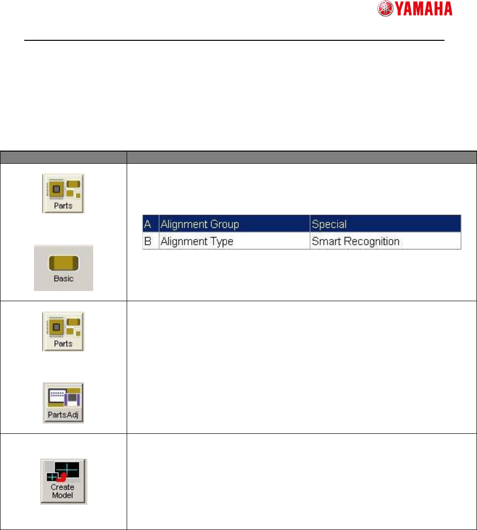
4. Using Method
4.1. Create parts data
First, create parts data for Smart Recognition as follows.
Menu Item
↓
Set [Alignment Group] to “Special”,
and [Align Type] to “Smart Recognition”.
Modify the parameters such as [Body Size], [Search Area (mm)],
and [Lighting Level] which are necessary for parts recognition
↓
Press the [Parts Adj] button to open the [Parts Adjust] screen.
Press the [Create Model] button.
Create model data, referring to the next section.
SMTSoftwareEngineeringGroup
IMOperationsYAMAHAMOTORCO.,LTD.
MDOC-SOFT50185
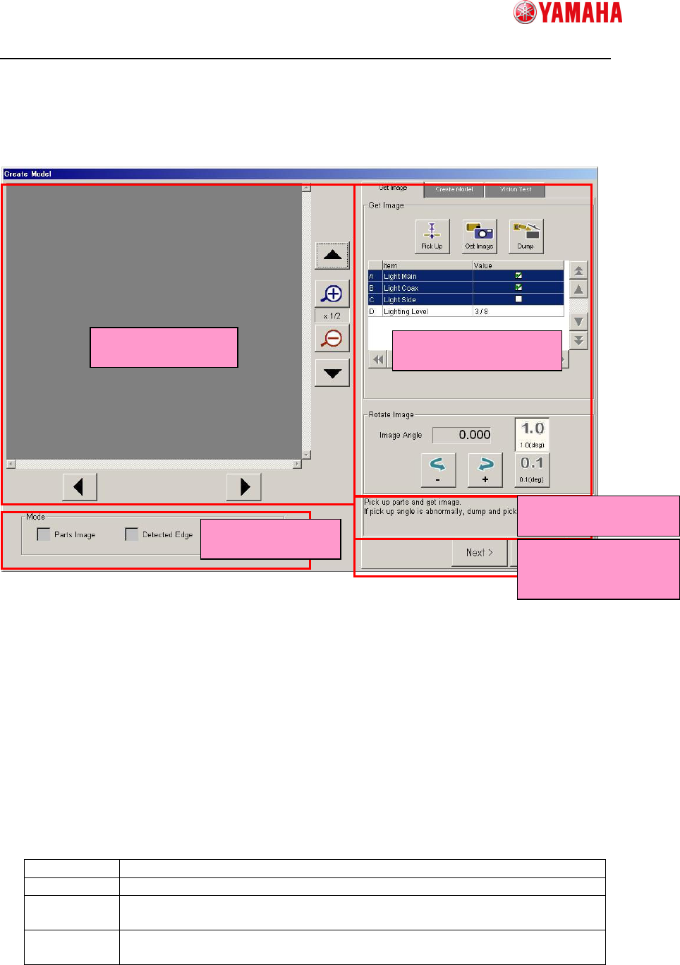
4.2. Create model data
4.2.1 Screen Structure
① Vision Window
Displays vision images such as captured image and edge image.
② Mode
Allows you to select an image type to display on Vision Window.
③ Operation Window
Allows you to operate the model creation process here throughout Capturing Image,
Creating Model, and Vision Test. This screen is displayed in the wizard format.
④ Guide Message
Displays guide messages you need to do next.
⑤ Screen Change Buttons
Next Goes to the next screen.
Back Goes back to the previous screen.
OK Saves the model data you are creating in the parts adjust data and goes
back to the parts adjust screen.
Cancel Cancels all model data you are creating and goes back to the parts
adjust screen.
①
①①
①Vision Window
③
③③
③Operation Window
②
②②
②Mode
④
④④
④Guide Message
⑤
⑤⑤
⑤Screen Change
Button