Vista Sensors and Motors.pdf - 第13页
SENSORS AND MOTORS REED SWITCH S ENSOR Chapter Issue 1 Sep 02 Technical Reference Manual 20.13 REED SWITCH SENSOR Descriptio n A reed swit ch sensor i s fitted t o the machine lid bolt actuator and remote board stop rot …
SENSORS AND MOTORS
OPTO SENSORS
20.12 Technical Reference Manual Chapter Issue 1 Sep 02
Testing/Adjustment If the sensor fails to operate, confirm the sensor is faulty as follows:
1. Disconnect the through beam opto.
2. Short out the signal to earth on the socket.
3. Check that the relevant MultiMove LED is illuminated, if so the sensor is
defective.
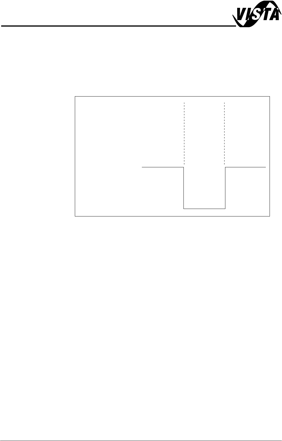
Figure 20-10 Voltage Diagram
Vane
Out
In
Out
12V
0V
On
Off
Off
Indication Light
(Rail Lift Up optos only)
Signal
SENSORS AND MOTORS
REED SWITCH SENSOR
Chapter Issue 1 Sep 02 Technical Reference Manual 20.13
REED SWITCH SENSOR
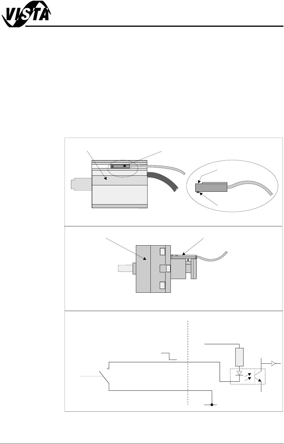
Description A reed switch sensor is fitted to the machine lid bolt actuator and remote board
stop rotary actuator. The reed switch is activated by a magnet fitted to either
the piston or drive shaft of the actuator.
One side of the switch is connected to the input, the other side of the reed switch
is connected to 0V. The input is connected to +12V via a pull up resistor (on
MultiMove or NextMove card), so under normal conditions the input is pulled
high. When the reed switch is activated by a magnet, the reed switch closes
and pulls the input down to 0V (low).
For ProFlow reed switch sensor information refer to the ProFlow chapter (Drives
and Sensors) of this manual.
Figure 20-11 Reed Switch Schematic
Digital Input
MultiMove/NextMove Card
V+ (User)
Opto-isolator
(Red)
(Black)
2K
0V (User)
12V
0V
N0
(normally open)
Locking Screw
Sensor
Pneumatic Cylinder Reed Switch
Pneumatic Cylinder with Reed Switch
Rotary Actuator
Rotary Actuator with Reed Switch
Board Stop In Reed Switch
SENSORS AND MOTORS
REED SWITCH SENSOR
20.14 Technical Reference Manual Chapter Issue 1 Sep 02
Testing/
Adjustment
Setting of the sensor is necessary in order to:
• Ensure that switching takes place in the correct position
• Ensure correct sensing, ie closing when piston extended/retracted
NOTE
For adjustment of ProFlow paste low sensor refer to ProFlow chapter of this
manual.
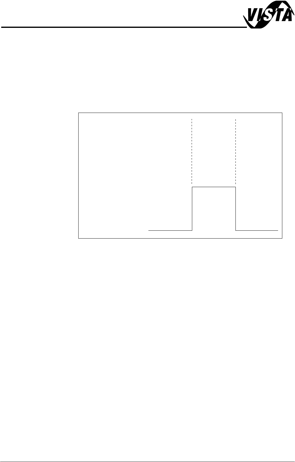
Figure 20-12 Voltage Diagram
Magnetic Piston Retracted Extended Retracted
12V
0V
Closed ClosedOpen
Reed Switch
Signal