Vista Sensors and Motors.pdf - 第24页
SENSORS AND MOTORS MOTORS 20.24 Technical Reference Manual Chapter Issue 1 Sep 02 Drive Output The servo driv e card convert s the demand volt age into a Pulse Wid th Modulated (PWM) si gnal which outputs dire ctly to th…
SENSORS AND MOTORS
MOTORS
Chapter Issue 1 Sep 02 Technical Reference Manual 20.23
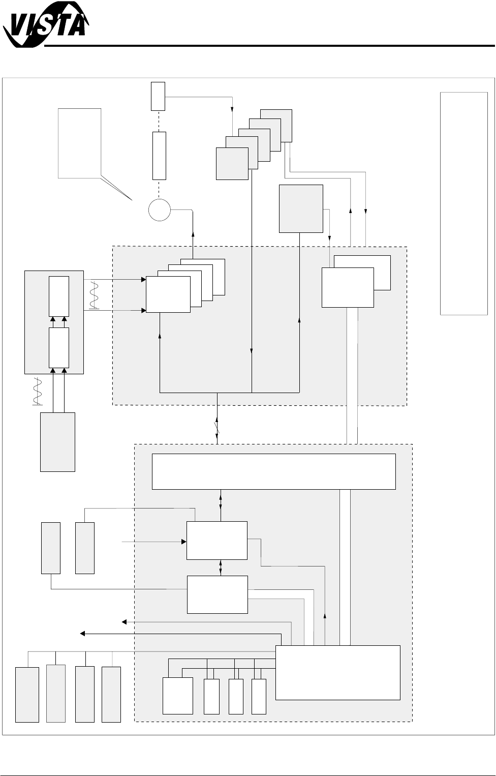
Figure 20-22 Servo System Schematic
Servo Motors
Encoder
Home
Axis 0
Servo
Drive
Axis 1
Axis 2
Axis 3
Dmd 0,1,2,3
CAN Bus
Camera X
Camera Y
Rising Table
Print Carriage
Machine Controller
100 Way
I/O Breakout Boards
A
B
C
D
E
Critical Real Time I/Ps
16 I/Ps, O/Ps
per card
Multi-
Interface
Unit
NOTE
The CAN Bus forms part of the 100 way connection
between the Machine PC and Controller enclosures
X13
X12
Multi-
Move
M
Host
Comms
Parallel
Printer
PCI Bus
ISA Bus
Machine PC
P.S.U.
HDD
Keyboard
Touchscreen
Camera
24v (U/S)
PCI 3
Vision
Card
Vision
P. C.
Adaptor
ISA 5
CDROM
FDD
P
r
o
c
e
s
s
o
r
ISA 3
Mouse
Lighting
Monitor
ISA 10
N
e
x
t
M
o
v
e
44V ac
44V ac
Con 3
Con 2
M23 ac Power
Module
M24 dc Power
Module
SENSORS AND MOTORS
MOTORS
20.24 Technical Reference Manual Chapter Issue 1 Sep 02
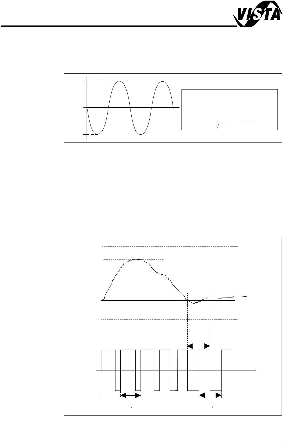
Drive Output The servo drive card converts the demand voltage into a Pulse Width Modulated
(PWM) signal which outputs directly to the motor. The amplitude of this
waveform is equivalent to the servo drive Bus voltage which is 1.4142 times
greater than the ac input voltage.
Figure 20-23 Peak and RMS Voltage
The Servo Drive Output figure shows servo drive PWM output against demand
input. As demand increases so the duty cycle changes such that the positive
‘ON’ time is greater than the negative ‘ON’ time resulting in an overall positive
current flow to the motor armature. Armature current is proportional to torque
hence the servo drive is known as a current or torque amplifier.
NOTE
When the motor is under a no load condition, ie stationary, the duty cycle is
50%.
Figure 20-24 Servo Drive Output
0
-62V
+62V
44V ac output from secondary of
transformer *
* RMS
==
=Peak 62
2
44V
1.4142
0
-62V
+62V
Duty Cycle Changes with Demand
Amplitude = bus voltage
50% duty
cycle
40 uS
40 uS
+10V
6V
60% demand
Forward motion
Stationary
low demand
-10V
SENSORS AND MOTORS
MOTORS
Chapter Issue 1 Sep 02 Technical Reference Manual 20.25
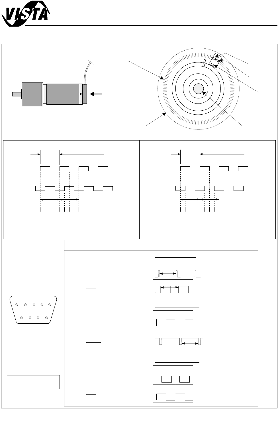
Figure 20-25 Encoder
Channel B
Channel A
Index
Glass Disc
Motor Shaft
5 4 3 2 1
9 8 7 6
1
+5V : Power to Encoder
Output from NextMove
Input to NextMove
Input to NextMove
Input to NextMove
Input to NextMove
Input to NextMove
Input to NextMove
Input to NextMove
Input to NextMove
Index Pulse
SCRN
CHA
GND : 0V Signal
CHB
2
3
4
5
6
7
8
9
Pin No. Signal Name
Type
CHB
INDEX
CHA
Wave Form
*
5V
0V
30mS
30mS
60mS
Example of print
carriage @ 100mm/Sec
*
Channel B
Channel A
Print Carriage
Rising Table, Camera X, Camera Y
90 deg. phase difference
Counts
Encoder Resolution
0
12
3
4
5
7
68
1Pulse=4Counts
1 Rev = 500 Pulses = 2000 Counts
1 Count = 0.18 degrees
1 Pulse
Encoder Resolution
1 Pulse = 4 Counts
1 Rev = 1000 Pulses = 4000 Counts
1 Count = 0.09 degrees
Channel B
Channel A
90 deg. phase difference
Counts
0
12
3
4
5
7
68
1 Pulse
Enlarged View on Arrow A
Renco Encoder
Sensors
A
500 or 1000 pulses