Vista Sensors and Motors.pdf - 第19页
SENSORS AND MOTORS PRESSU RE SENSO R Chapter Issue 1 Sep 02 Technical Reference Manual 20.19 T esting/ Adjustment For adjus tment refer to the Pneumatics Modul e Chapter . The sensor may be tested eit her in circuit or d…
SENSORS AND MOTORS
PRESSURE SENSOR
20.18 Technical Reference Manual Chapter Issue 1 Sep 02
PRESSURE SENSOR
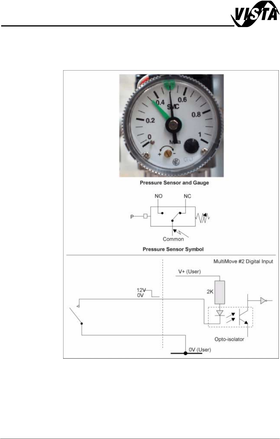
Description The pressure sensor switch is wired as a normally open (NO) switch which is
closed by the air pressure exceeding the set point.
Figure 20-17 Pressure Sensor Schematic
SENSORS AND MOTORS
PRESSURE SENSOR
Chapter Issue 1 Sep 02 Technical Reference Manual 20.19
Testing/
Adjustment
For adjustment refer to the Pneumatics Module Chapter.
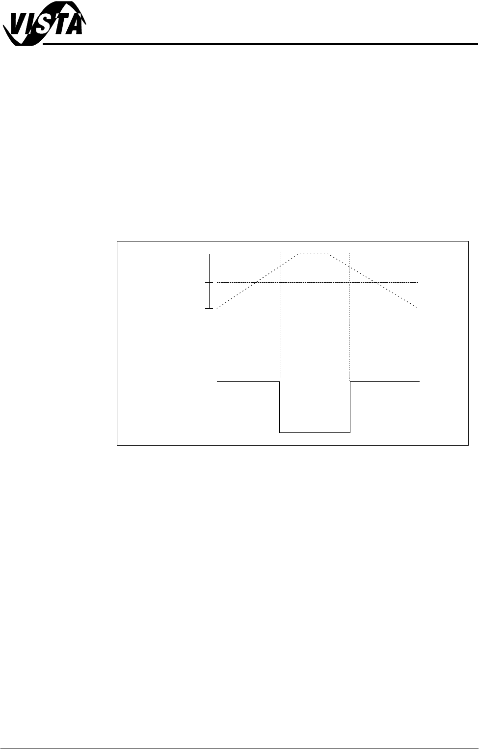
The sensor may be tested either in circuit or disconnected:
In circuit -
• Monitor the voltage at signal IN 0 whilst increasing the pressure from zero
using the main regulator. As the air pressure exceeds the set point value
the voltage is pulled down to 0V.
Disconnected -
• Measure continuity across the switch whilst increasing the pressure from
zero using the main regulator. As the air pressure exceeds the set point
value the contacts close.
Figure 20-18 Pressure Diagram
Indicated
Pressure
12V
0V
Open
Circuit
Closed
Circuit
Open
Circuit
Set Point
Contact
Continuity
Digital I/P
Signal
5
3
bar
0
SENSORS AND MOTORS
MOTORS
20.20 Technical Reference Manual Chapter Issue 1 Sep 02
MOTORS There are three types of motor used on the machine as follows:
• Stepper Motor
• Servo Motor
• DC Motor
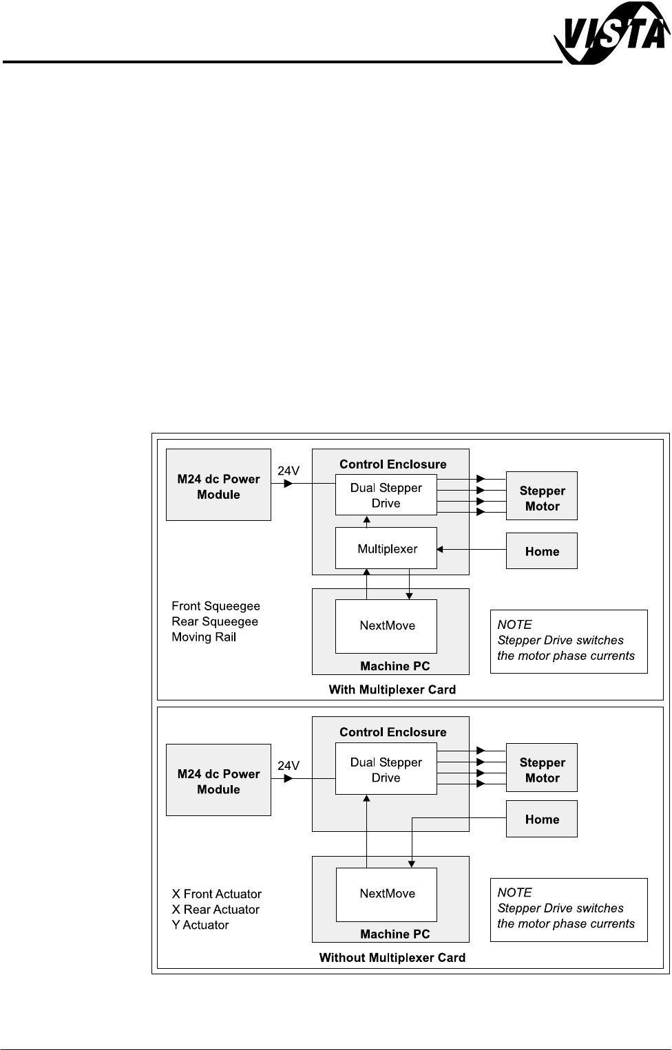
Stepper Motor A stepper motor rotates its shaft by a precise angular amount each time it is
actuated. A stepper motor is used for the following functions:
• Screen Actuators (XF, XR and Y)
• Front and Rear Squeegee
• Moving Rail
NOTE
With the stepper system there is no feedback from the motor to the controller,
therefore should the system encounter excess mechanical friction it simply
stalls.
Figure 20-19 Stepper System Basic Layout