Vista Sensors and Motors.pdf - 第5页
SENSORS AND MOTORS HALL EFFECT SENSOR Chapter Issue 1 Sep 02 Technical Reference Manual 20.5 HALL EFFECT SENSOR Descriptio n A Hall ef fect transduc er and magnet are combined in a common package, with a gap between t he…
SENSORS AND MOTORS
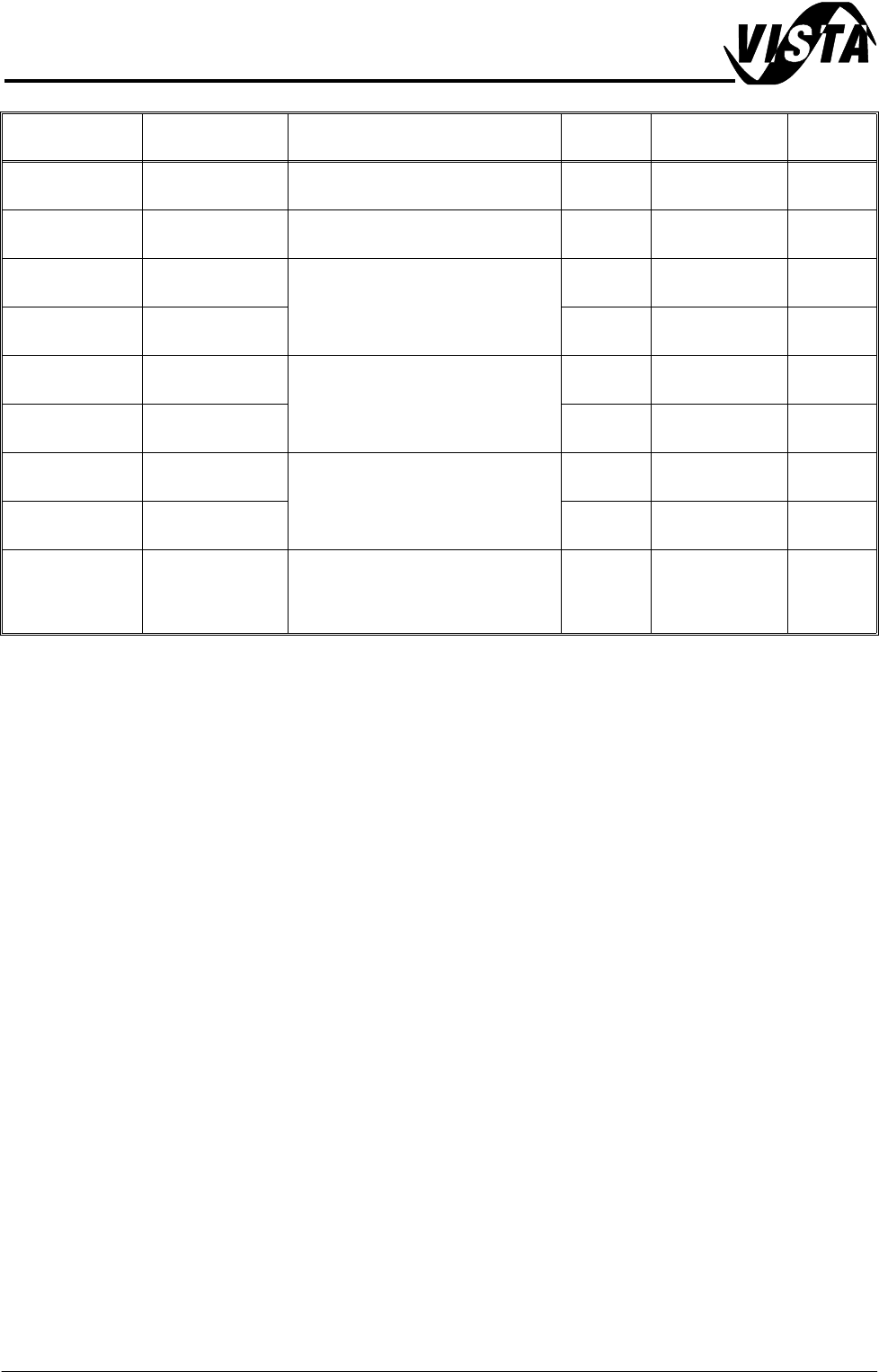
SENSOR TABLE
20.4 Technical Reference Manual Chapter Issue 1 Sep 02
Solvent Low Refractive Opto Fitted in right hand side of solvent
tank
8SE12 MultiMove X13 DIG IN 7
Rear Squeegee
Home
Microswitch Front of spline support block (left)
squeegee mechanism
9SE05 Multiplexer Rear Sqy
Home
X Forward Fine
Home
Hall Effect
Within X forward screen actuator
9SE7 NextMove DIG IN 10
X Forward
Coarse Home
Hall Effect 9SE8 NextMove DIG IN 11
X Rear Fine
Home
Hall Effect
Within X rear screen actuator
9SE9 NextMove DIG IN 8
X Rear Coarse
Home
Hall Effect 9SE10 NextMove DIG IN 9
Y Actuator Fine
Home
Hall Effect
Within Y screen actuator
9SE16 NextMove DIG IN 12
Y Actuator
Coarse Home
Hall Effect 9SE17 NextMove DIG IN 13
Temperature and
Humidity
Humidity:
capacitive
Temp:
NTC resistive
Print carriage front (left side) beside
squeegee/ProFlow mechanism
9SE20 NextMove
Name Type Sensor Location Sensor
Ident
Input Card Signal
SENSORS AND MOTORS
HALL EFFECT SENSOR
Chapter Issue 1 Sep 02 Technical Reference Manual 20.5
HALL EFFECT SENSOR
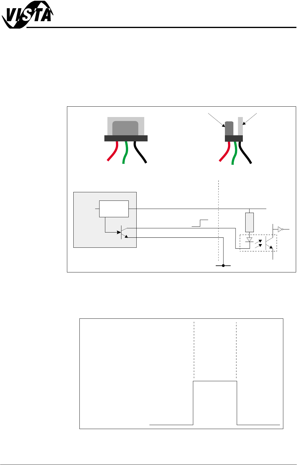
Description A Hall effect transducer and magnet are combined in a common package, with
a gap between the transducer and magnet. With power ON and the gap clear,
the output transistor is switched on and the signal voltage is pulled down to 0V.
When a ferrous vane is passed through the gap, the Hall effect is cancelled,
switching off the output transistor and the signal is 12V via the digital input
circuit.
Figure 20-3 Hall Effect Schematic
Testing/
Adjustment
With Power ON and a voltmeter connected with +ve to signal (green) and -ve
to 0V (black), the following results should be obtained:
Figure 20-4 Voltage Diagram
Hall Effect Sensor
Magnet
Transducer
Hall Effect
Magnet
MultiMove / NextMove /
Multiplexer Digital Input
V+ (User)
Opto-isolator
2K
0V (User)
0V
12V
12V
0V
0V
Signal
(Red)
(Green)
(Black)
V+
Control
Circuit
Pin 1
Pin 2
Pin 3
Ferrous Vane
Clear
Present
Clear
12V
0V
On OnOff
Hall Effect
Signal
SENSORS AND MOTORS
OPTO SENSORS
20.6 Technical Reference Manual Chapter Issue 1 Sep 02
OPTO SENSORS
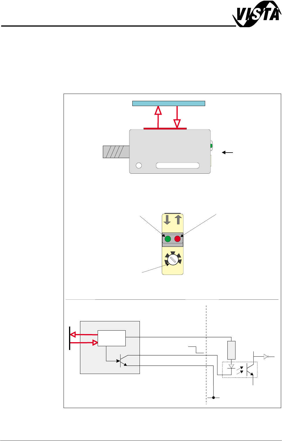
Diffuse Type Opto Diffuse sensors can distinguish between objects with various reflection proper-
ties, these emit a beam of pulsed red light which is reflected as the target enters
the scanning distance. When the intensity of the received light exceeds that set
by the sensitivity control, ie when the board is detected, the sensor output is
switched ON.
Figure 20-5 Diffuse Type Opto
NextMove Digital Input
V+ (User)
Opto-isolator
0V (User)
Pin 1 12V
12V
NPN
0V
Pin 3 0V
Pin 2 Signal
Control
Circuit
2K
A
Reflective OptoReflective Opto
Sensitivity Control
Sets the switching
threshold.
Red LED
Lights when intensity of
received light exceeds the
switching threshold.
Green LED
Lights when intensity of
received light exceeds the
switching threshold
by more than 50%.
View on Arrow A
STA.
SENS.
OUT