Vista Sensors and Motors.pdf - 第3页
SENSORS AND MOTORS SENSOR TABLE Chapter Issue 1 Sep 02 Technical Reference Manual 20.3 SENSOR T ABLE The followi ng table list s all machine sensors in alphabetica l order . Name T ype Sensor Lo cation Senso r Ident Inpu…
SENSORS AND MOTORS
SENSORS
20.2 Technical Reference Manual Chapter Issue 1 Sep 02
Solid State
Switches
The machine uses the following types of solid state sensor switches:
• Hall Effect Sensors
• Opto Sensors
• Capacitive Proximity Sensor
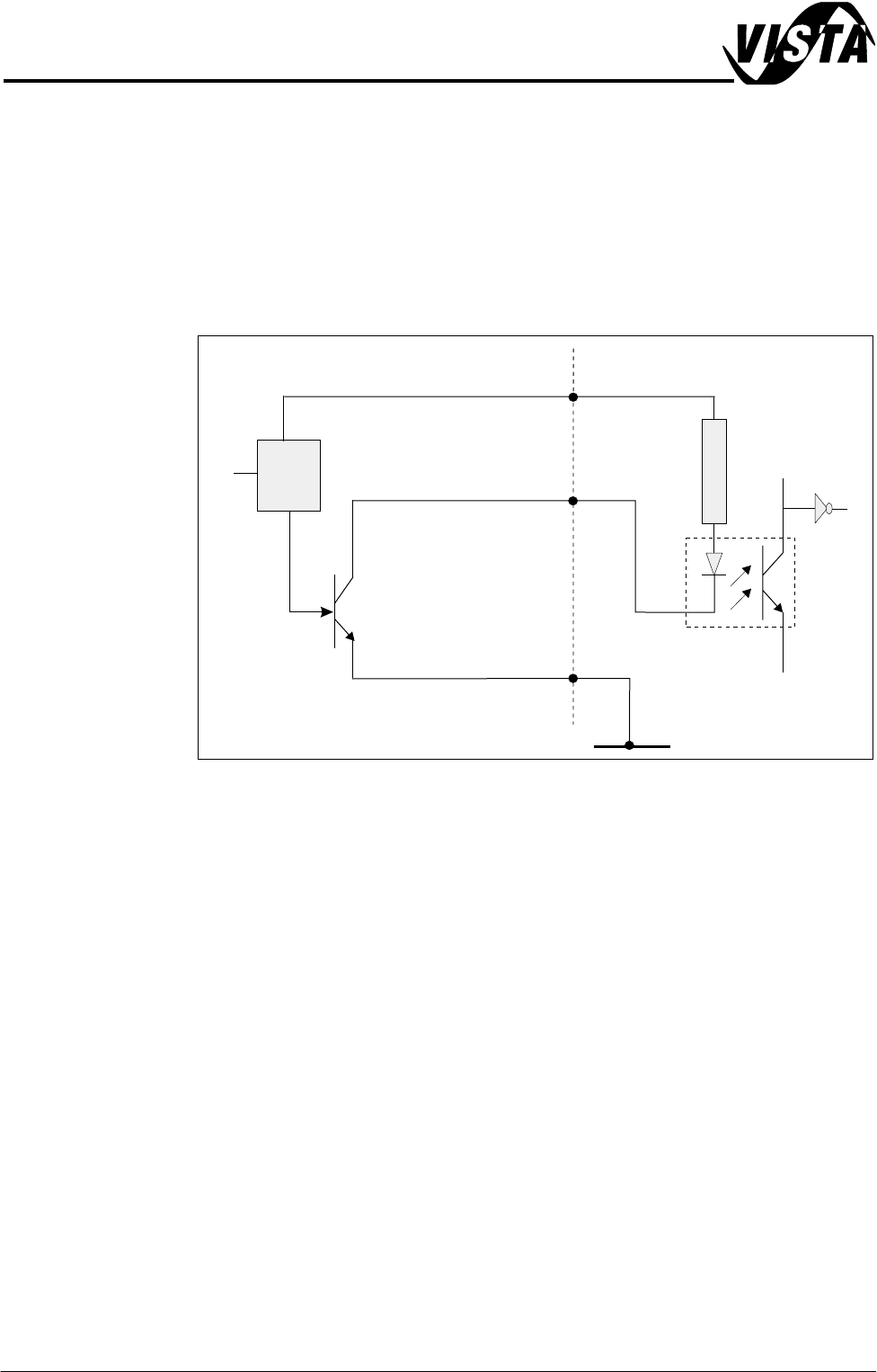
In all cases to initiate a logic 1 (on state) at the input, the sensor must connect
the signal input to 0V.
Figure 20-2 Typical Solid State Schematic
Testing Solid state sensors can only be tested in circuit as they require a logic supply
voltage.
1. Check for the 12V logic supply to the sensor.
2. Activate the sensor according to type and measure the voltage at the output
terminal with respect to 0V. The sensor output signal should change
between approximately 0V and 12V (see individual sensor descriptions for
more details).
NOTE
Full listing of digital inputs are listed in the Diagnostics chapter of the User
manual.
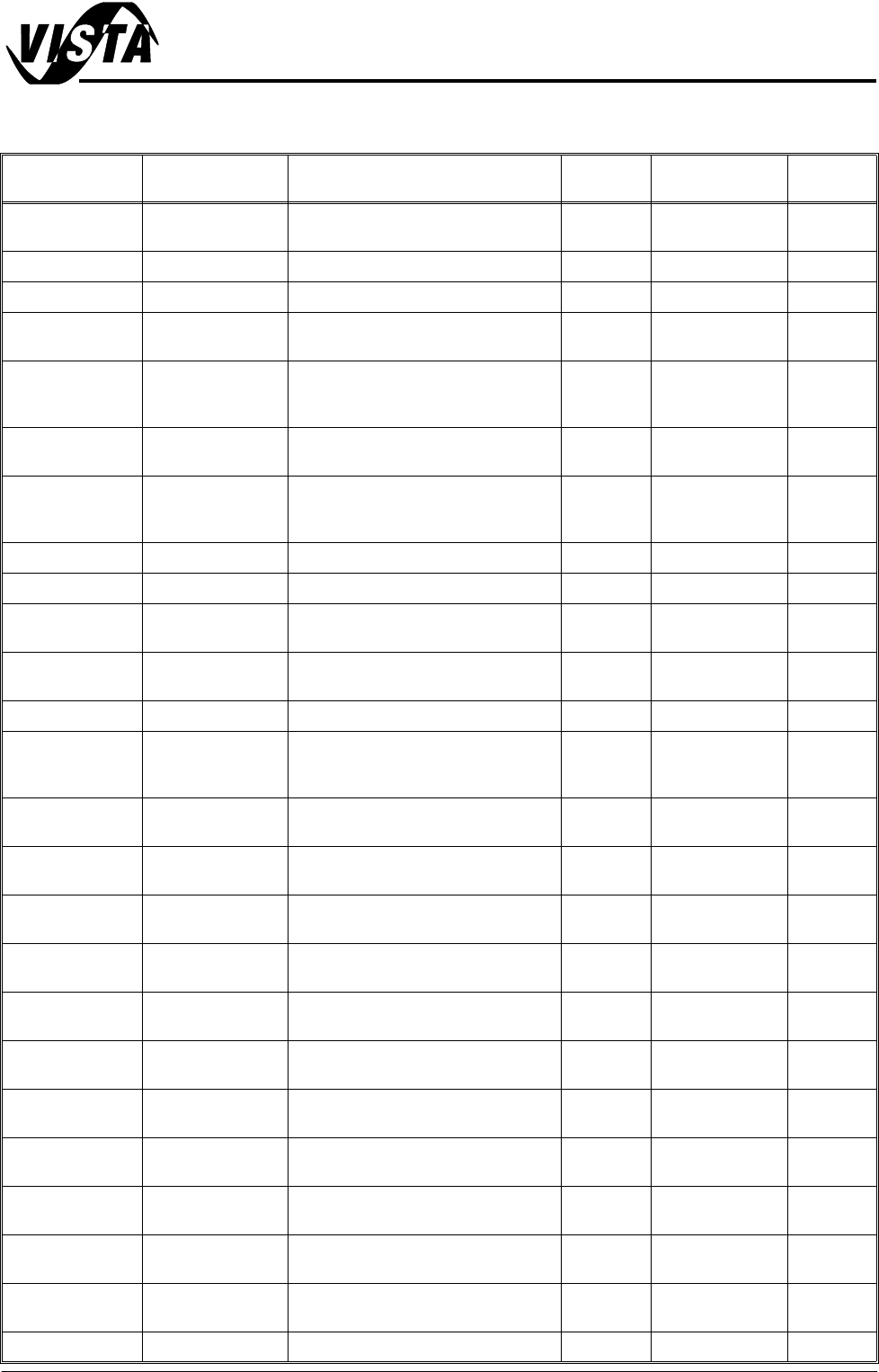
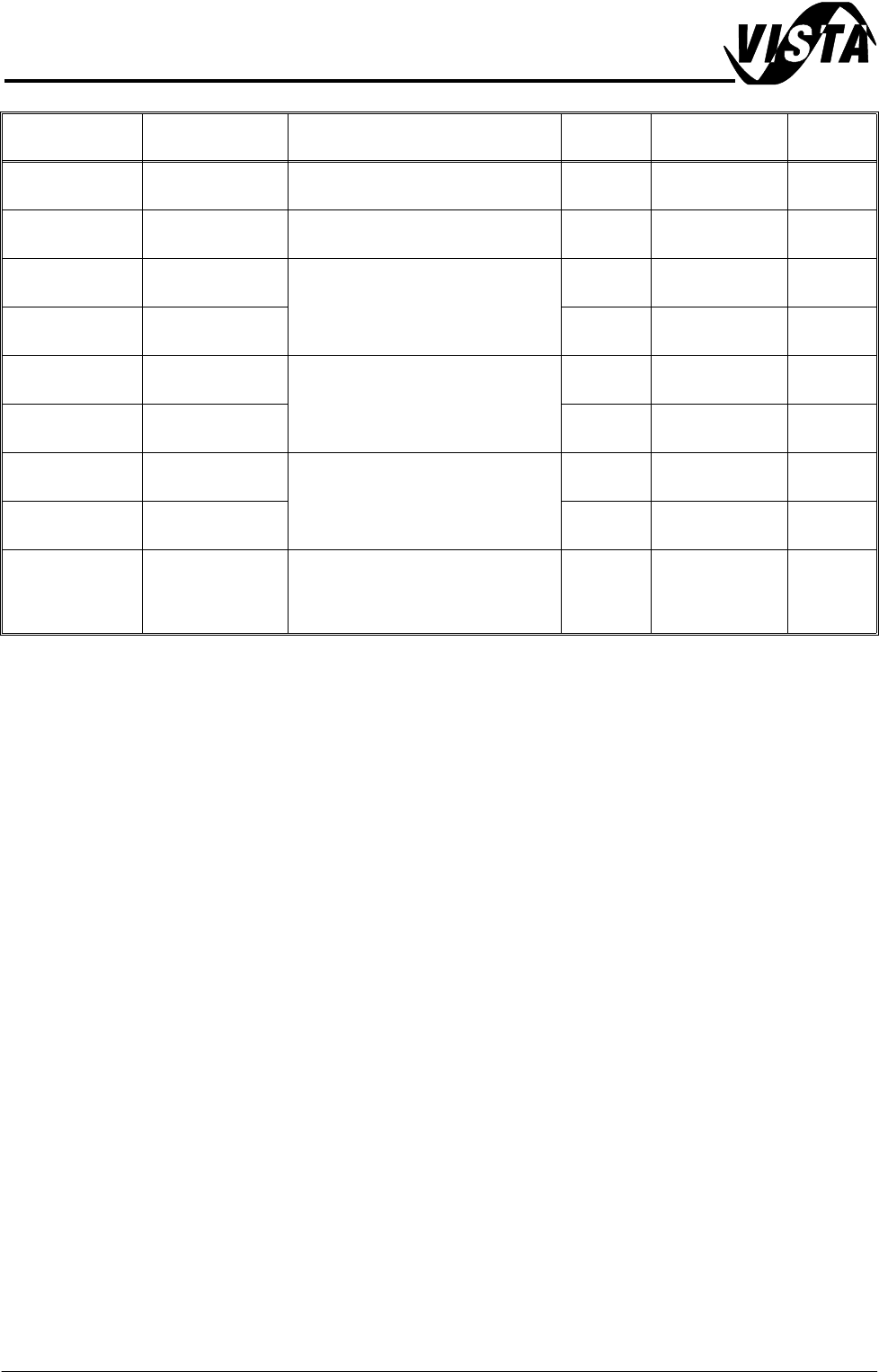
Sensor Location Sensor locations are detailed in the Sensor Table of this chapter. Machine
location for individual sensors are detailed in the respective module chapter
overview sections, ie Solvent Low Sensor - can be found in the Under Screen
Cleaner chapter (Sensors section).
Digital Input
V+ (User)
12V
Opto-isolator
2K
0V (User)
Signal I/P
Control
Circuit
Solid State
Sensor
SENSORS AND MOTORS
SENSOR TABLE
Chapter Issue 1 Sep 02 Technical Reference Manual 20.3
SENSOR TABLE The following table lists all machine sensors in alphabetical order.
Name Type Sensor Location Sensor
Ident
Input Card Signal
Air Pressure Pressure Part of mains air regulator on rear of
machine frame
8SE11 MultiMove X12 DIG IN 0
Board at Left Diffuse Front rail, left side 8SE8 NextMove DIG IN 16
Board at Right Diffuse Front rail, right side 8SE7 NextMove DIG IN 17
Board at Stop
(camera)
Diffuse/Back-
ground
Camera carriage 10SE07 NextMove DIG IN 22
Board at Stop
(remote board
stop)
Diffuse/Back-
ground
Remote board stop 10SE26 NextMove DIG IN 22
Board Stop In
(camera)
Thro’ Beam Opto Mounted on board stop, camera car-
riage
10SE20 NextMove DIG IN 23
Board Stop In
(remote board
stop)
Reed Switch Mounted on rotary actuator, remote
board stop
10SE25 NextMove DIG IN 23
Camera X Home Hall Effect Left on X camera carriage 10SE01 NextMove DIG IN 5
Camera Y Home Hall Effect Rear on Y camera carriage support 10SE02 NextMove DIG IN 15
Front Cover Inter-
lock
Safety Switch Top cover support frame, front left
side
9SW01 MultiMove X13 DIG IN 4
(shared)
Front Squeegee
Home
Microswitch Front of spline support block (right)
squeegee mechanism
9SE04 Multiplexer Front Sqy
Home
Lid Bolt Extended Reed Switch Located on shock bolt solenoid 9SW3 MultiMove X12 DIG IN 2
Moving Rail
Home
Thro’ Beam Opto Right side of rising table at:
rear (front rail justified)
front (rear rail justified)
8SE6 Multiplexer Rail Home
Print Carriage
Home
Hall Effect Right hand side of right print carriage
rail, rear of machine
9SE3 NextMove DIG IN 6
ProFlow Cassette
Low
Reed Switch Left hand side of ProFlow pressure
mechanism unit
M18SE01 MultiMove X12 DIG IN 6
ProFlow Home Microswitch Under motor support plate on the
ProFlow printhead mechanism
9SE05 Stepper Multi-
plexer
Rail Lifted Left Thro’ Beam Opto Left side of rising table attached to
rear rail
8SE5 NextMove DIG IN 3
Rail Lifted Right Thro’ Beam Opto Right side of rising table attached to
rear rail
8SE4 NextMove DIG IN 4
Rear Cover Inter-
lock
Safety Switch Top cover bracket, rear 9SW2 MultiMove X13 DIG IN 4
(shared)
Rising Table
Home
Hall Effect Left side of rising table 8SE01 NextMove DIG IN 0
Rising Table
Interlock
Thro’ Beam Opto Left side of rising table 8SE03 NextMove DIG IN 2
Rising Table Limit Hall Effect Left side of rising table, with upper
and lower limit vanes
8SE02 NextMove DIG IN 1
Screen Clean
Home
Hall Effect Front left hand side of printhead 8SE10 MultiMove X13 DIG IN 5
Front Cover Inter-
lock
Safety Switch Top cover support frame, front left
side
9SW01 MultiMove X13 DIG IN 4
(shared)
Screen at Centre Thro’ Beam Opto Both sides of chase casting 13SE07 MultiMove X12 DIG IN 1
SENSORS AND MOTORS
SENSOR TABLE
20.4 Technical Reference Manual Chapter Issue 1 Sep 02
Solvent Low Refractive Opto Fitted in right hand side of solvent
tank
8SE12 MultiMove X13 DIG IN 7
Rear Squeegee
Home
Microswitch Front of spline support block (left)
squeegee mechanism
9SE05 Multiplexer Rear Sqy
Home
X Forward Fine
Home
Hall Effect
Within X forward screen actuator
9SE7 NextMove DIG IN 10
X Forward
Coarse Home
Hall Effect 9SE8 NextMove DIG IN 11
X Rear Fine
Home
Hall Effect
Within X rear screen actuator
9SE9 NextMove DIG IN 8
X Rear Coarse
Home
Hall Effect 9SE10 NextMove DIG IN 9
Y Actuator Fine
Home
Hall Effect
Within Y screen actuator
9SE16 NextMove DIG IN 12
Y Actuator
Coarse Home
Hall Effect 9SE17 NextMove DIG IN 13
Temperature and
Humidity
Humidity:
capacitive
Temp:
NTC resistive
Print carriage front (left side) beside
squeegee/ProFlow mechanism
9SE20 NextMove
Name Type Sensor Location Sensor
Ident
Input Card Signal