Vista Sensors and Motors.pdf - 第23页
SENSORS AND MOTORS MOTORS Chapter Issue 1 Sep 02 Technical Reference Manual 20.23 Figure 20- 22 Servo Syst em Schematic Servo Motors Encoder Home Axis 0 Servo Drive Axis 1 Axis 2 Axis 3 Dmd 0,1,2,3 CAN Bus Camera X Camer…
SENSORS AND MOTORS
MOTORS
20.22 Technical Reference Manual Chapter Issue 1 Sep 02
Servo Motor A servo motor is a motor in which the rotational position or speed is controlled
by electrical feedback signals. This feedback is generated by a control system
that measures the difference between the actual and desired position and then
takes action to reduce that difference. A servo motor is used for the following
functions:
• Camera X and Y Axes
• Rising Table
• Print Carriage
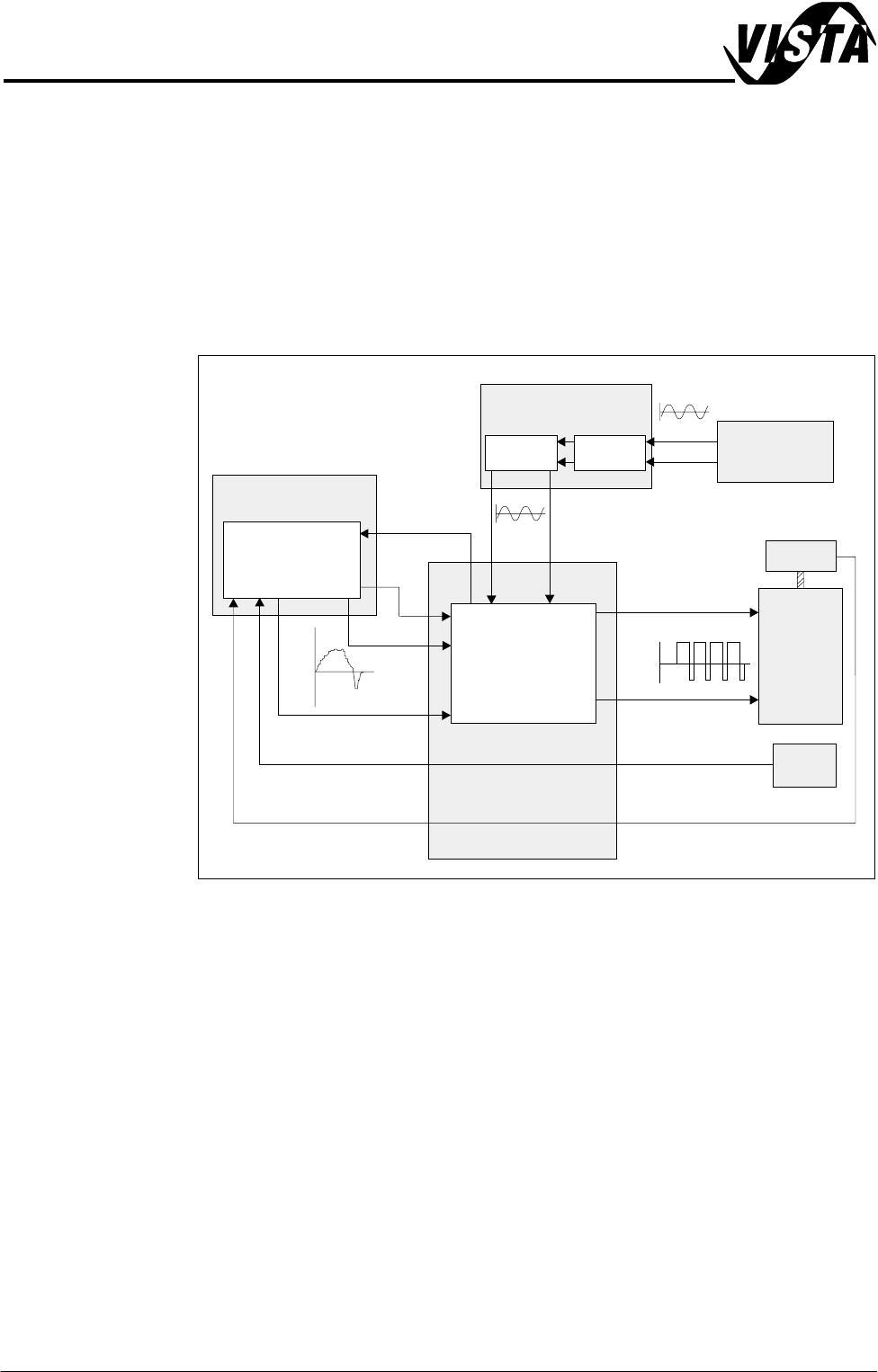
Figure 20-21 Servo System Basic Layout
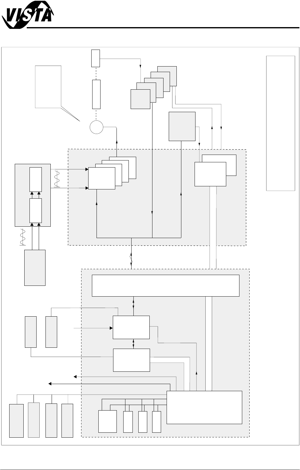
The Servo System Schematic Figure shows a typical servo system, overall
control of the system is by the Machine PC. When axis movement is required
a command is sent via the machine PC NextMove controller to the servo drive
cards in the machine controller.
Demand The demand output from the NextMove controller is in the form of a ±10V dc
level generated by the Nextmove card (Servo System Basic Layout figure
refers). The error signals are derived from the encoder unit.
NextMove
Card
+VE
Motor +VE
Encoder Out
Servo
Motor
Motor -VE
-VE
Demand
Output
to Motor
Error
Enable
Servo Drive
+62V
25kHz PWM
-62V
44V ac
44V ac
+10V
-10V
Encoder
Machine PC
Machine Controller
M24 dc Power
Module
M23 ac Power
Module
Con 3
Con 2
Home
SENSORS AND MOTORS
MOTORS
Chapter Issue 1 Sep 02 Technical Reference Manual 20.23
Figure 20-22 Servo System Schematic
Servo Motors
Encoder
Home
Axis 0
Servo
Drive
Axis 1
Axis 2
Axis 3
Dmd 0,1,2,3
CAN Bus
Camera X
Camera Y
Rising Table
Print Carriage
Machine Controller
100 Way
I/O Breakout Boards
A
B
C
D
E
Critical Real Time I/Ps
16 I/Ps, O/Ps
per card
Multi-
Interface
Unit
NOTE
The CAN Bus forms part of the 100 way connection
between the Machine PC and Controller enclosures
X13
X12
Multi-
Move
M
Host
Comms
Parallel
Printer
PCI Bus
ISA Bus
Machine PC
P.S.U.
HDD
Keyboard
Touchscreen
Camera
24v (U/S)
PCI 3
Vision
Card
Vision
P. C.
Adaptor
ISA 5
CDROM
FDD
P
r
o
c
e
s
s
o
r
ISA 3
Mouse
Lighting
Monitor
ISA 10
N
e
x
t
M
o
v
e
44V ac
44V ac
Con 3
Con 2
M23 ac Power
Module
M24 dc Power
Module
SENSORS AND MOTORS
MOTORS
20.24 Technical Reference Manual Chapter Issue 1 Sep 02
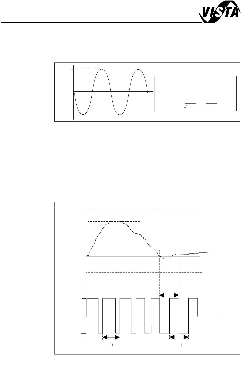
Drive Output The servo drive card converts the demand voltage into a Pulse Width Modulated
(PWM) signal which outputs directly to the motor. The amplitude of this
waveform is equivalent to the servo drive Bus voltage which is 1.4142 times
greater than the ac input voltage.
Figure 20-23 Peak and RMS Voltage
The Servo Drive Output figure shows servo drive PWM output against demand
input. As demand increases so the duty cycle changes such that the positive
‘ON’ time is greater than the negative ‘ON’ time resulting in an overall positive
current flow to the motor armature. Armature current is proportional to torque
hence the servo drive is known as a current or torque amplifier.
NOTE
When the motor is under a no load condition, ie stationary, the duty cycle is
50%.
Figure 20-24 Servo Drive Output
0
-62V
+62V
44V ac output from secondary of
transformer *
* RMS
==
=Peak 62
2
44V
1.4142
0
-62V
+62V
Duty Cycle Changes with Demand
Amplitude = bus voltage
50% duty
cycle
40 uS
40 uS
+10V
6V
60% demand
Forward motion
Stationary
low demand
-10V