LA 302 Pressure Controller Manual.pdf - 第22页
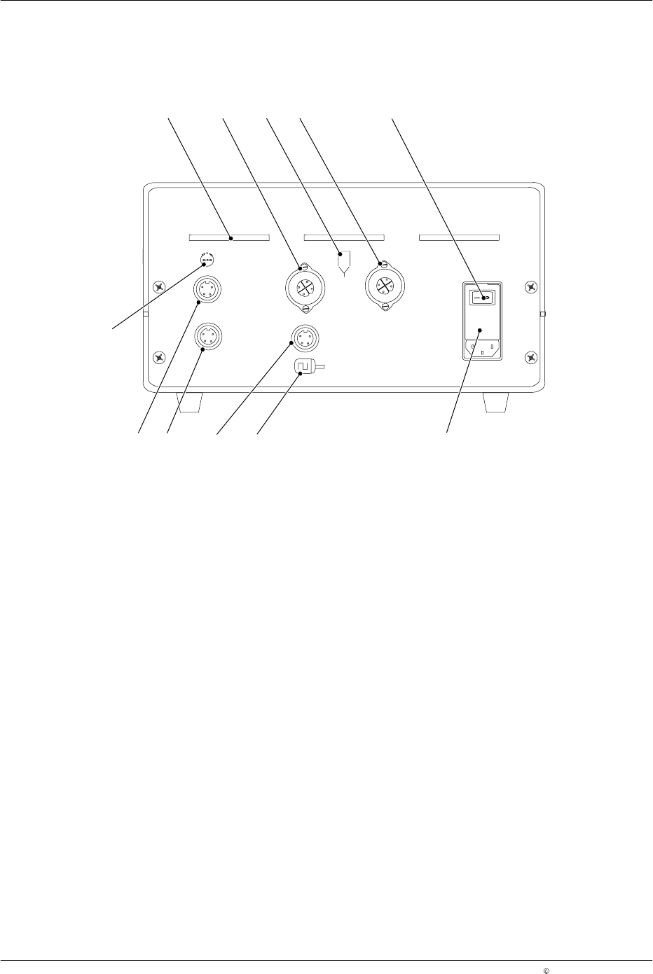
Description 2-6 P/N 71 19797A 2006 Nordson Corporation LA 302 Issued 06/06 Ba ck 3 5 2 4 10 9 6 7 1 8 1 1 Fig. 2-3 1 V entilation slit 2 Output for adhesive gun 1 3 Symbol for adhesive guns 4 Output for adhesive gun 2 5 …
Description
2-5
P/N 7119797A
2006 Nordson Corporation
LA 302
Issued 06/06
Front
1 2
3 8
7
6
5
4
11
9
13
15
12
10
14
23
22
21
20
17
24
19
18
16
29
27
26
28 25
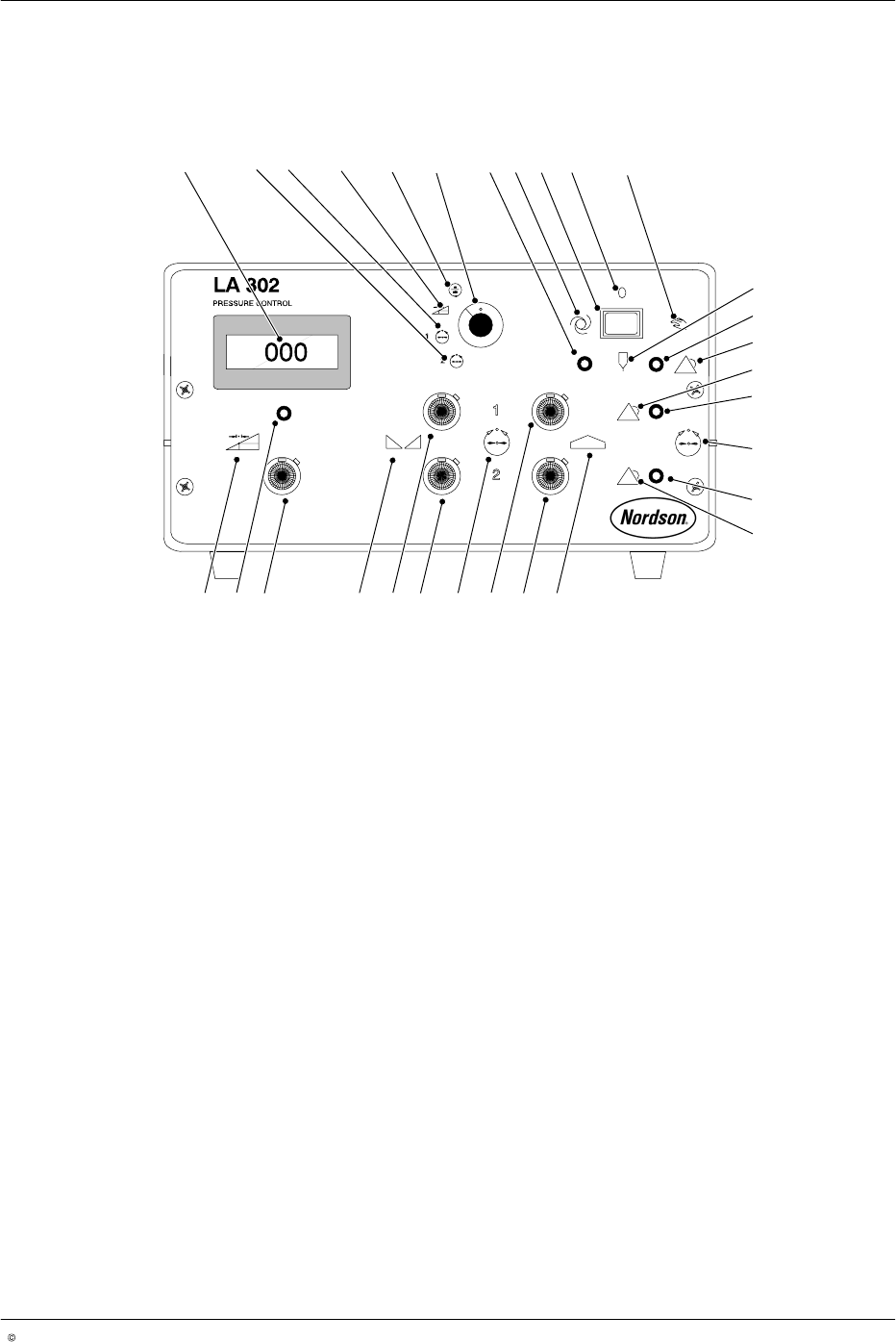
Fig. 2-2
1 Display (7-segment display)
2 Setting for pressure display,
proportional pressure control
valve 2
3 Setting for pressure display,
proportional pressure control
valve 1
4 Setting for minimum speed
display
5 Setting for production speed
display
6 Mode switch (A)
7 LED (1) for automatic and manual
mode
8 Symbol for automatic mode (left
switch position)
9 Switch automatic/manual mode
(B)
10 Central position (without function)
11 Symbol for manual mode (right
switch position)
12 Symbol for adhesive gun
13 Alarm LED (2) for adhesive gun
14 Alarm symbol for adhesive gun
15 Alarm symbol for proportional
pressure control valve 1
16 Alarm LED (4) for proportional
valve 1
17 Symbol for pressure setting of
proportional pressure control
valve 1 and 2
18 Alarm LED (5) for proportional
valve 2
19 Alarm symbol for proportional
pressure control valve 2
20 Symbol for maximum pressure
21 Potentiometer (G) for maximum
pressure (proportional pressure
control valve 2)
22 Potentiometer (D) for maximum
pressure (proportional pressure
control valve 1)
23 Symbol for pressure settings of
proportional pressure control
valve 1 and 2
24 Potentiometer (F) for minimum
pressure (proportional pressure
control valve 2)
25 Potentiometer (C) for minimum
pressure (proportional pressure
control valve 1)
26 Symbol for minimum pressure
27 Potentiometer (E) for minimum
speed
28 LED (3) to indicate that speed
has fallen below minimum speed
29 Symbol for minimum speed
setting
NOTE: Beginning here, mode switches and potentiometers on the front of
the pressure controller will be designated alphabetically as mode switch /
potentiometer (A), (B), (C), ... beginning at the top left and moving to the
right. The LEDs are designated LED (1), LED (2), ... beginning at the top
left and moving to the right.
Description
2-6
P/N 7119797A
2006 Nordson Corporation
LA 302
Issued 06/06
Back
3
5
2 4
10
9 6
7
1
8
11
Fig. 2-3
1 Ventilation slit
2 Output for adhesive gun 1
3 Symbol for adhesive guns
4 Output for adhesive gun 2
5 Mains switch
6 Unit port
7 Encoder symbol
8 Encoder input
9 Proportional pressure control
valve output
10 Proportional pressure control
valve output
11 Pressure output symbol
Installation
3-1
P/N 7119797A
2006 Nordson Corporation
LA 302
Issued 06/06
Section 3
Installation
WARNING: Allow only qualified personnel to perform the following tasks.
Observe and follow the safety instructions in this document and all other
related documentation.
Transport
Transport the unit such as to prevent damage. Do not throw the unit. Use
suitable packing material, e.g. Styrofoam and sturdy cardboard. Refer to
Technical Data for weight.
Protect the unit from humidity, dust, jolts and vibrations.
Unpacking
Unpack the unit carefully to prevent damage. Then check for any damage
caused during shipping.
Save the packing material for later use. Otherwise reuse the material or
dispose of it properly according to local regulations.
Setup
Protect the unit from humidity, excessive dust accumulation and vibrations.
Do not block ventilation slits (1, Fig. 3-1).
Refer to Technical Data for dimensions.