LA 302 Pressure Controller Manual.pdf - 第28页
Installation 3-6 P/N 71 19797A 2006 Nordson Corporation LA 302 Issued 06/06 Initial Startup NOTE: The compressed air used should be filtered and dry . If necessary , a water separator or a pneumatic dehumidifier should b…
Installation
3-5
P/N 7119797A
2006 Nordson Corporation
LA 302
Issued 06/06
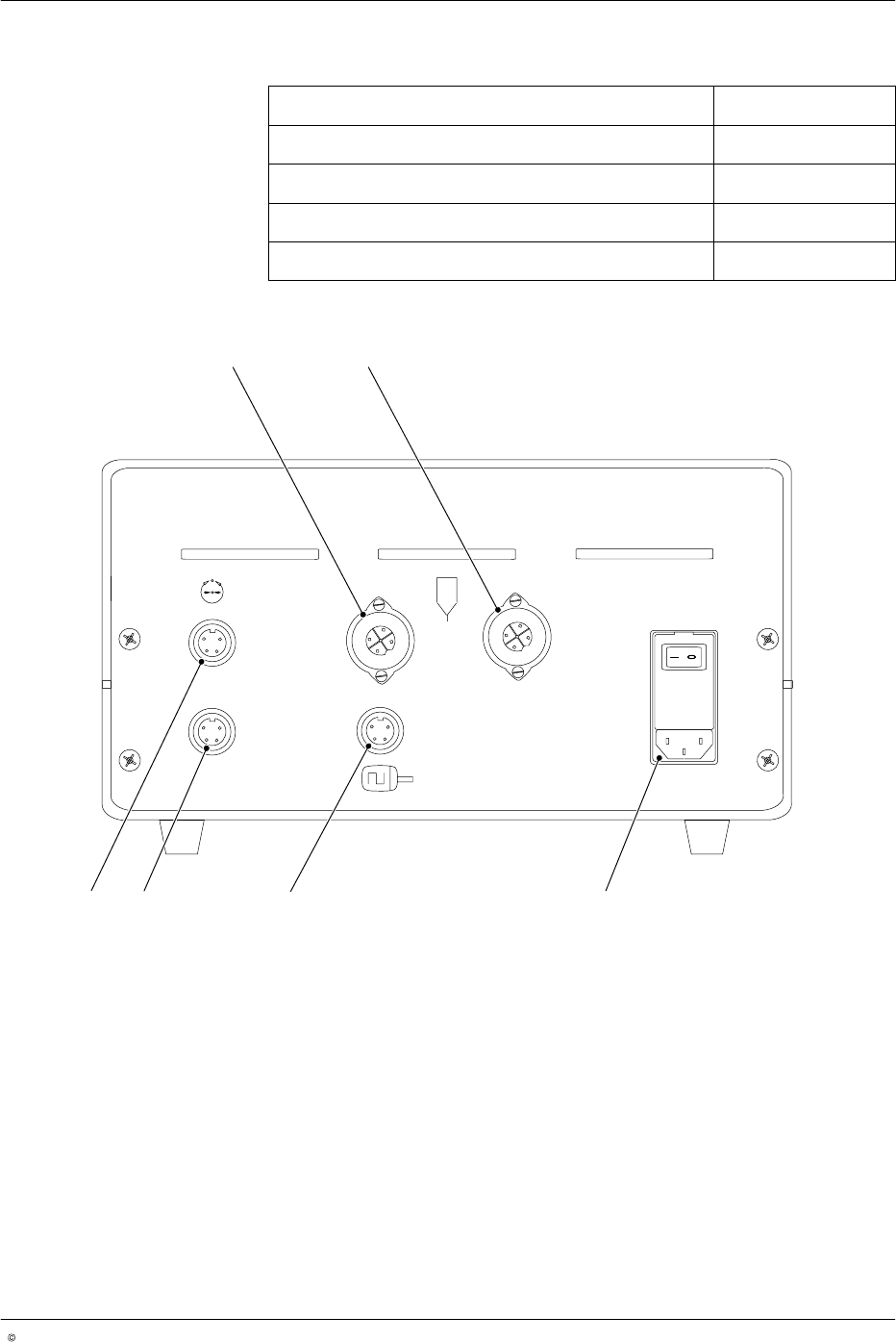
Accessories
Required accessories Sleeve
Encoder with cable 8
Power cable for proportional valve 9, 10
Adhesive gun with cable 2, 4
Power cable 6
2
4
9
10
8 6
Fig. 3-6

Installation
3-6
P/N 7119797A
2006 Nordson Corporation
LA 302
Issued 06/06
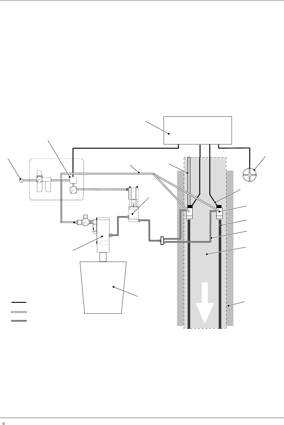
Initial Startup
NOTE: The compressed air used should be filtered and dry. If necessary, a
water separator or a pneumatic dehumidifier should be used to prevent ice
from forming.
It is imperative to perform the following steps in the stated order for initial
startup.
The stated position numbers refer to Figure 3-7.
1. Connect the compressed air to the air conditioning unit (1).
2. Stop compressed air supply on the air conditioning unit.
3. Connect the compressed air supply to the container pump (14).
4. Connect the compressed air supply to the adhesive gun (15).
5. Connect the proportional valve compressed air outlet (2) to the adhesive
pressure regulator (12).
6. Connect the adhesive outlet of the container pump to the pressure
regulator.
7. Connect the glue outlet of the adhesive pressure regulator to the
adhesive guns (8).
8. Electrically connect the LA 302 to the adhesive gun (5).
9. Electrically connect the LA 302 to the proportional pressure control valve
(2).
10. Electrically connect the LA 302 to the encoder (4), and mechanically
connect the production machine and encoder through the gear box.
11. Start the production machine and determine the lowest possible
production speed.
12. Switch on the applicator LA 302 with the mains switch (5, Fig. 2-3).
NOTE: Mode switches and potentiometers on the front of the pressure
controller will be designated alphabetically as mode switch / potentiometer
(A), (B), (C), ... beginning at the left and moving to the right. The LEDs are
designated LED (1), LED (2), ... beginning at the top left and moving to the
right.
13. Set the minimum speed (lowest speed at which the adhesive gun
nozzles open) to the desired initial speed (but not < 4 m/min) using the
potentiometer (E) on the LA 302. LED (3) should go off.
14. Slowly increase the compressed air on the air conditioning unit
(1, Fig. 3-7).
15. Run the system at minimum production speed and set the minimum
pressure for proportional pressure control valve 1 with potentiometer (C)
or the minimum pressure for proportional pressure control valve 2 with
potentiometer (F) such that the glue bead is even and cohesive.
Installation
3-7
P/N 7119797A
2006 Nordson Corporation
LA 302
Issued 06/06
16. Run the system at maximum production speed and set the maximum
pressure for proportional pressure control valve 1 with potentiometer (D)
or the maximum pressure for proportional pressure control valve 2 with
potentiometer (G) such that the glue bead is even and cohesive
(production machine speed may need to be throttled). Lock the setting.
NOTE: If the quality of the glue bead is not satisfactory, continue to adjust
the minimum speed setting on the production machine and on the LA 302
and adjust the respective minimum pressure until the glue bead is correct. If
the production machine is run at a speed below the minimum speed set on
the LA 302, pressure control does not occur.
1
2
3
4
12
14
13
10
5
7
9
8
6
11
15
Electrical components
Compressed air
Adhesive
Fig. 3-7