00191369-02.pdf - 第111页
User Manual HS-50 3 Introduction and Basic Concepts Software Version SR.501.xx 12/99 Issue US 3.2 Principles of t he Graphic User In terface 111 t I I t Meaning of Other Icons and Markings 3 If a trac k error , mach ine …
3 Introduction and Basic Concepts User Manual HS-50
3.2 Principles of the Graphic User Interface Software Version SR.501.xx 12/99 Issue US
110
t IIt
Å Check the box "Abort processing PCB" if the PCB is to be transported to the output conveyor
without further processing.
Å Check the box "PCB not to be assembled in PA2" if the PCB is to be processed on processing
conveyor 1 and is then to be transported to the output conveyor without being processed on
processing conveyor 2.
Å Click the Accept button.
3
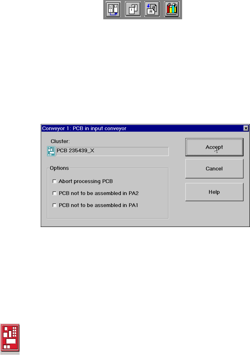
If the PCB is located on the input conveyor, the following dialog box is opened. 3
3
Å Check the box "Abort processing PCB" if the PCB is to be transported to the output conveyor
without further processing.
Å Check the box "PCB not to be assembled in PA2" if the PCB is to be processed on processing
conveyor 1 only and is then to be transported to the output conveyor without being processed
on processing conveyor 2.
Å Check the box "PCB not to be assembled in PA1" if the PCB is to be transported through pro-
cessing conveyor 1 without being processed and is then to be processed on processing con-
veyor 2.
Å Click the Accept button.
3
Processing of PCB aborted 3
If processing of the PCB has been aborted by a click on the PCB icon (see example above), the
color of the PCB icon changes to red.
The icon is also displayed in red if a PCB is manually placed on processing conveyor 1 or 2. The
PCB is not recognized by the system and is transported to the output conveyor. 3
User Manual HS-50 3 Introduction and Basic Concepts
Software Version SR.501.xx 12/99 Issue US 3.2 Principles of the Graphic User Interface
111
t IIt
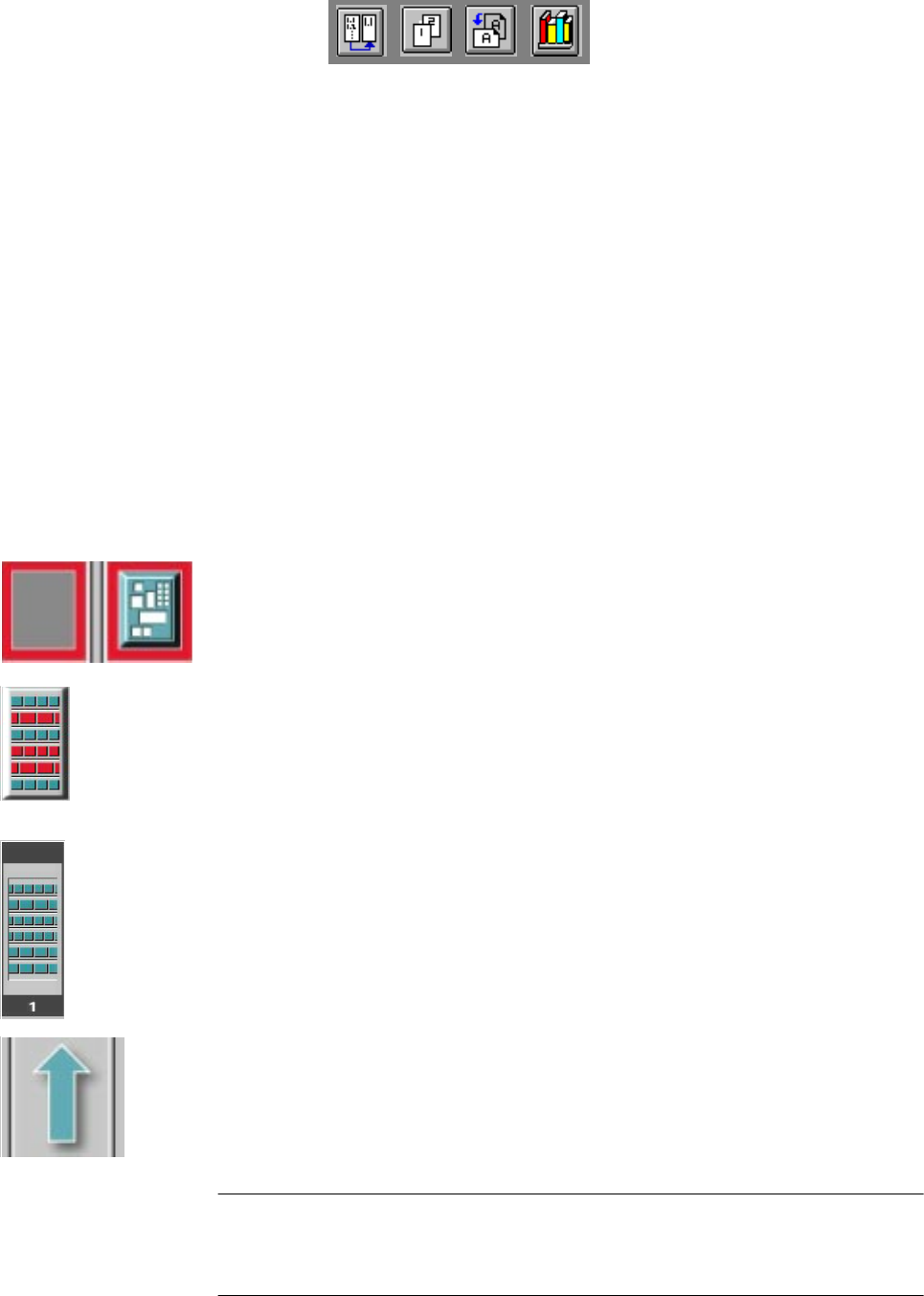
Meaning of Other Icons and Markings 3
If a track error, machine error or conveyor error occurs, then the corresponding graphic is high-
lighted in red (see examples below).
3
Examples: If an error occurs in a processing area, then this is displayed with a red
border.
You can abort processing of the PCB which is located in this area by clicking the
PCB icon.
If a conveyor error occurs during transport, this is indicated by the presence of red
bars on the left and right.
If a track error occurs (e.g. missing components), then individual parts of the
graphic which correspond to the layout of the current feeder location are displayed
against a red background. In addition, the graphic is displayed with a contour.
If you click this graphic, you can use the corresponding function to "refill" the
location (see Chapter 4). 3
3
Machine error 3
3
3
Components missing at feeder location 3
3
3
3
3
Feeder location full 3
3
3
Conveyor set to "Transport through" 3
3
3
3
NOTE
This means that the "Process PCB" function is deactivated in the machine options.
The PCBs are passed through the entire transport process without being processed.
3
3 Introduction and Basic Concepts User Manual HS-50
3.2 Principles of the Graphic User Interface Software Version SR.501.xx 12/99 Issue US
112
t IIt
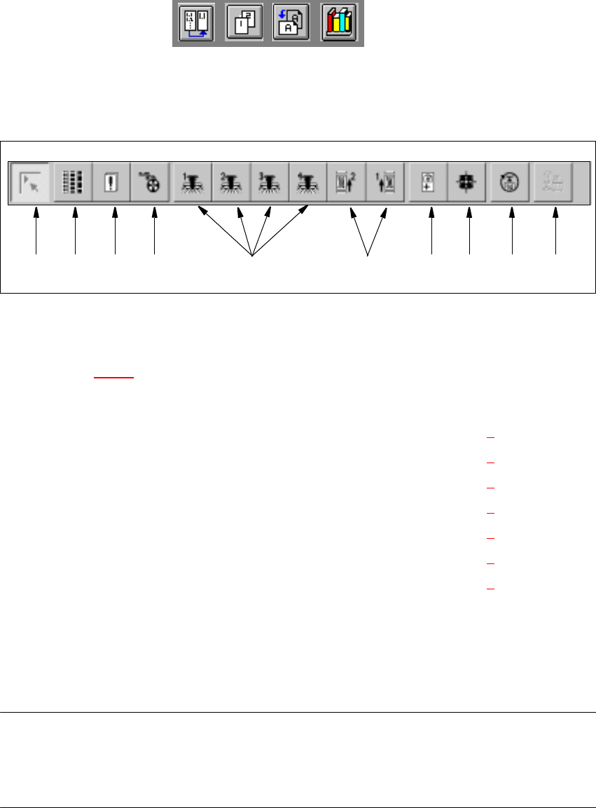
3.2.2.2 Toolbar in Main View
3
Fig. 3.2 - 2 Toolbar in main view
3
Key to Figure 3.2 - 2
(1) Main view
(2) Set-up, placement functions (for a description see Chapter 4
)
(3) Error, placement functions (for a description see Chapter 4
)
(4) Component feeder, placement functions (for a description see Chapter 4
)
(5) Gantry 1 to 4, single functions (for a description see Chapter 5
)
(6) Conveyor 1 and 2, single functions (for a description see Chapter 5
)
(7) Teach fiducials, vision functions (for a description see Chapter 6
)
(8) Test component, vision functions (for a description see Chapter 6
)
(9) Start SITEST test program (for a description see User’s Manual
"Test Program SITEST")
(10) GEM interface
3
NOTES to points 6 and 10
The single functions for Conveyor 2 can only be called if a twin conveyor has been configured.
The GEM interface functions cannot be called unless this has been configured.
The "GEM Interface" option cannot be configured in the current software version. 3
Å Click the required button in the toolbar.
The user interface is switched to the corresponding view.
The button corresponding to the view which is currently active itself becomes inactive.
3
1 8 9 10765432