00191369-02.pdf - 第43页
User Manual HS-50 1 Introduction Software Vers ion SR.501.xx 12/99 Issue US 1.13 Overview of the modules - revolver head 43 t I I t 1.13 O vervi ew of the mod ules - r evolv er hea d 1.13 .1 Structure of t he 12-se gment…
1 Introduction User Manual HS-50
1.12 Overview of the modules - gantries Software Version SR.501.xx 12/99 Issue US
42
t IIt
The Y-axis essentially consists of the following main modules: 1
– Y-axis linear drive with permanent magnet (1) and adapter plate (2)
– Y-axis guide system
– Y-axis measuring system
1
The Y-axis is driven by a linear motor. The secondary part of the drive is made up of permanent
magnets and is mounted on the machine frame. The primary part is bolted to the gantry (adapter
plate). An anti-crash circuit prevents the traversing paths of the gantries meeting. 1
1.12.5 Technical data for the Y-axis
Drive Direct, linear motor
Maximum speed 2.5 m/sec.
Traversing path of the gantries. calculated
from the center of the machine:
Gantry 1 - 688.5 mm
Gantry 2 - 768.5 mm
Gantry 3 - 688.5 mm
Gantry 4 - 768.5 mm
Distance measuring system Metal linear scale
Scale length 1530 mm
Resolution 1 µm
User Manual HS-50 1 Introduction
Software Version SR.501.xx 12/99 Issue US 1.13 Overview of the modules - revolver head
43
t IIt
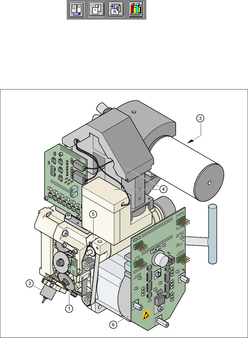
1.13 Overview of the modules - revolver head
1.13.1 Structure of the 12-segment revolver head
1
Fig. 1.13 - 1 Structure of the 12-segment revolver head
1
1
(1) Star with 12 sleeves (2) Motor for "Reject" valve adjustment drive
(3) Turning station (4) Component vision system
(5) Z-axis drive (6) Star motor

1 Introduction User Manual HS-50
1.13 Overview of the modules - revolver head Software Version SR.501.xx 12/99 Issue US
44
t IIt
All the components are inserted with the same cycle time. Before the component is inserted, it is
measured by the optoelectronic vision system. 1
– The component vision camera creates an image of the current component.
– The precise position of the component is also determined.
– The package form of the current component is compared against the programmed package
form in order to identify it. Any components that cannot be identified are rejected.
– The turning station turns the component to the required placement position.
1.13.2 Description of the 12-segment revolver head
– The 12-segment revolver head works using the "collect & place" principle, i.e. the components
are held by the nozzles with the aid of a vacuum and, after one complete pick-up cycle, are
placed gently and accurately on the PCB with the aid of forced air. The vacuum in the nozzles
is also checked several times to determine whether the components were picked up and set
down correctly.
– The "adaptive" sensor stop mode of the z axis compensates for any irregularity of the PCB sur-
face when the components are set down.
– Defective components are rejected and are picked up again during a repair run.
1.13.3 Technical data - revolver head
Range of components
0402 to PLCC44, including BGA, µBGA, flip-chip,
TSOP, QFP, PLCC, SO to SO32, DRAM
Maximum height 6 mm
Minimum lead pitch 0.5 mm
Minimum dimensions 0.5 mm x 1.0 mm
Maximum dimensions 18.7 mm x 18.7 mm
Maximum weight 2 g
Maximum travel of the z axis 16 mm
Programmable set-down force 2.4 to 5.0 N
Nozzle types 9xx
Benchmark placement speed 12,500 components/hour
Angular accuracy 0.7° at 4 sigma
Placement accuracy
± 90 µm at 4 sigma
± 135 µm at 6 sigma