00191369-02.pdf - 第31页
User Manual HS-50 1 Introduction Software Version S R.501.xx 12/99 Issue US 1.10 Setting up the placement system 31 t I I t 1.10 Setting up the placement syste m 1.10.1 T ransp ort dimensions The place ment s ystem m oun…
1 Introduction User Manual HS-50
1.9 Dimensions and weight of the placement system Software Version SR.501.xx 12/99 Issue US
30
t IIt
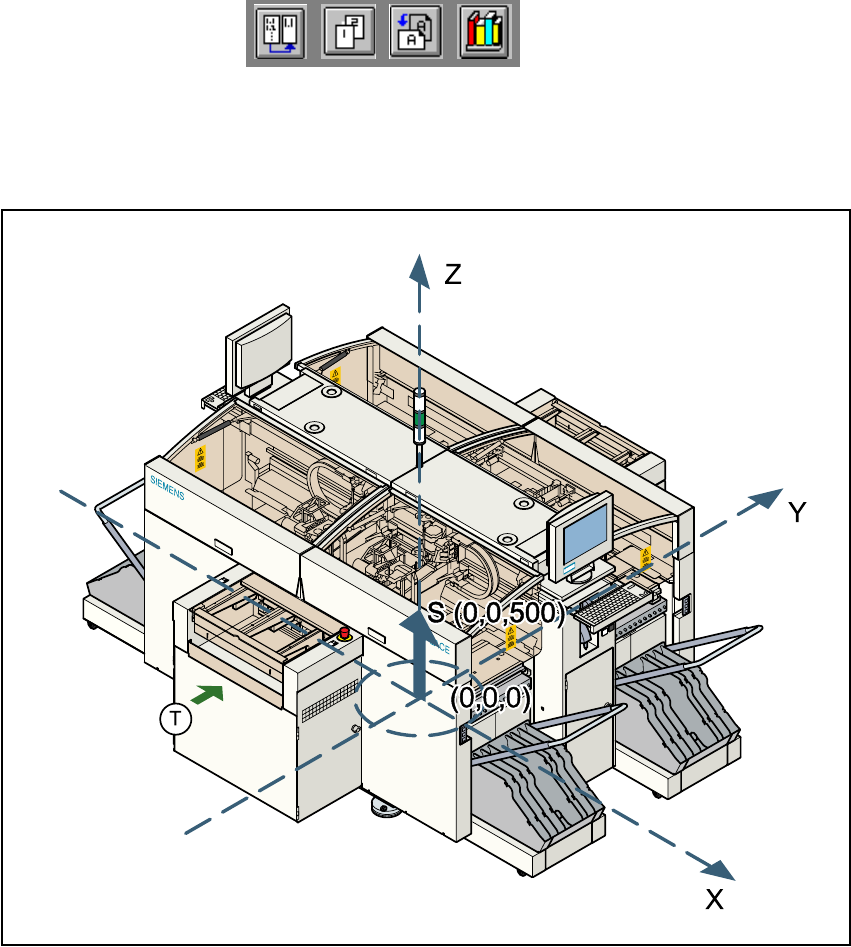
1.9.3 The placement system’s center of gravity
1
Fig. 1.9 - 2 The placement system’s center of gravity
X coordinate 0 mm 1
Y coordinate 0 mm 1
Z coordinate 500 mm high 1
T PCB transport direction 1
1
These center of gravity coordinates relate to placement systems with a PCB transport height of
830 mm. 1
User Manual HS-50 1 Introduction
Software Version SR.501.xx 12/99 Issue US 1.10 Setting up the placement system
31
t IIt
1.10 Setting up the placement system
1.10.1 Transport dimensions
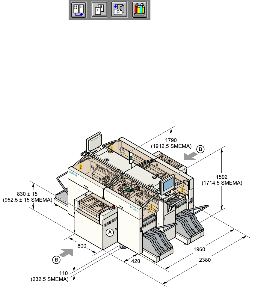
The placement system mounting kit (A) on the input side can be dismantled for transportation pur-
poses, which will reduce the width of the machine from 2380 mm to 1960 mm. 1
1
Fig. 1.10 - 1 Dimensions of the placement system during transportation and setting up
A Mounting kit which can be dismantled for transportation purposes. 1
B Points for attaching the fork-lift truck (fork length 2500 mm) 1
1
The PCB conveyor height is 830 mm ± 15 mm (or 952.5 mm ± 15 mm in accordance with the
SMEMA standard). The height specifications for the machine will change accordingly. 1

1 Introduction User Manual HS-50
1.10 Setting up the placement system Software Version SR.501.xx 12/99 Issue US
32
t IIt
1.10.2 Transport configuration and transportation
The following components are not installed when the placement system is delivered from the fac-
tory: 1
– keyboards
– monitors
– fault indicator lamps and
– component tables
Å Install the dismantled components for commissioning.
Å Use a fork-lift truck to transport the placement system:
– minimum fork length 2000 mm if the mounting kit is dismantled.
– minimum fork length 2500 mm if the mounting kit is still fitted.
Å Attach the fork-lift truck only at the indicated points.
1.10.3 Quality of the foundation
Å Ensure that
– you set up the placement system on a firm and non-vibrating foundation.
– the load bearing capacity per unit area of the foundation is greater than 1000 kg/m².
1.10.4 Compressed air supply
– The pressure of the compressed air supply must be 6.5 bar min.
– The compressed air must conform to the above specification.
This can be achieved with 1
– oil-free compressors, e.g. Atlas, Copco type ZR4
– compressed air washer/driers
– micro-filters, series X, e.g. from Zander
1.10.5 Power supply
– The power socket must be fused with the following fuse ratings:
3x32A for 3x204VAC 1
3x32A for 3x230VAC 1