00191369-02.pdf - 第46页
1 Introduction User Manual HS-50 1.14 Overview of the modules - vision systems Software Version SR.501.xx 12/99 Issue US 46 t I I t 1.14. 2 T echnical dat a - PCB vision syst em Fiducials Up to 3 per pl acement program L…

User Manual HS-50 1 Introduction
Software Version SR.501.xx 12/99 Issue US 1.14 Overview of the modules - vision systems
45
t IIt
1.14 Overview of the modules - vision systems
Each placement system has 1
– four component vision cameras on the placement heads and
– four PCB vision cameras on the underside of the X-axis gantries.
1
The vision evaluation units are located in the control unit for the placement system and the com-
ponent vision system is used to determine: 1
– the precise position of the components at the nozzle and
– the geometry of the package form.
1
The PCB vision system uses fiducials on the PCBs to determine: 1
– the position of the PCB,
– its rotation angle
– and the PCB delay.
1
The PCB vision system also uses fiducials on the feeder modules to determine the exact pick-up
position of components, which is particularly important for small components. 1
1.14.1 Technical data - component vision module on the 12-segment revolver head
Maximum component dimensions 18.7 mm x 18.7 mm
Range of components
0402 to PLCC44
including BGA, µBGA, flip-chip, TSOP, QFP
PLCC, SO to SO32, DRAM
Lead spacing > = 0.5 mm
Field of vision 24 mm x 24 mm
Illumination method Front-lighting (3 levels programmable as required)
1 Introduction User Manual HS-50
1.14 Overview of the modules - vision systems Software Version SR.501.xx 12/99 Issue US
46
t IIt
1.14.2 Technical data - PCB vision system
Fiducials Up to 3 per placement program
Local fiducials Up to 2 per component (may be of different types)
Library size Up to 255 fiducial types - system fiducials ≥ 249
Image processing Gray scale-based correlation
Illumination method Front-lighting
Recognition time per fiducial/ink spot 0.4 s
Field of vision 5.7 mm x 5.7 mm
User Manual HS-50 1 Introduction
Software Version SR.501.xx 12/99 Issue US 1.15 Overview of the modules - PCB conveyor
47
t IIt
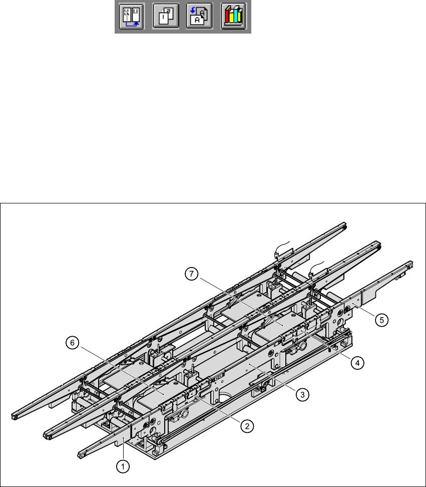
1.15 Overview of the modules - PCB conveyor
1.15.1 Structure of the PCB conveyor
The placement system is supplied with a single conveyor as standard. A dual conveyor is avail-
able as an option. 1
The left or the right side of the PCB conveyor can be used as the stationary side, as required. 1
1
Fig. 1.15 - 1 Structure of the PCB conveyor
(1)Input area
(2)Processing area 1
(3)Intermediate area
(4)Processing area 2
(5)Output area
(6)Lifting table (processing area 1)
(7)Lifting table (processing area 2)
1
1