00191369-02.pdf - 第64页
2 Operational Safety User Manual HS -50 2.2 Safety equipment Software Version SR.501.xx 12/99 Issue U S 64 t I I t 2.2 Safety equipme nt 2.2.1 Protect ive cove rs 2 Fig. 2.2 - 1 Protective cove rs 2 The travel ling ra ng…
User Manual HS-50 2 Operational Safety
Software Version SR.501.xx 12/99 Issue US 2.1 Safety instructions
63
t IIt
Å Swivel the component table handle up. The latching disk will also swivel up.
3/($6(127(
,I\RXFDQQRWVZLYHOWKHODWFKLQJGLVNXSWRLWVHQGSRVLWLRQWKHFURVVEHDPPXVWEHUDLVHG
Å )L[WKHOLIWLQJGHYLFHWRWKHFURVVEHDP
Å &DUHIXOO\RSHQWKHFURVVEHDPFODPS
Å 5DLVHWKHFURVVEHDPXQWLOWKHHQGRIWKHWXEHSURMHFWVDSSUR[PPRXWRIWKHFOD PS
Å 7LJKWHQWKHFURVVEHDPFODPS
Å 7KHQWXUQWKHDGMXVWLQJVFUHZWRWKHGHVLUHGGLPHQVLRQDQGORFNLQSODFHZLWK WKHORFNQXW
Å Then
carefully
open the cross-beam clamp.
Å Lower the cross-beam until the adjusting screw comes into contact with the latching disk.
Å Tighten the cross-beam clamp.
Å Then check the distance between the cross-beam and floor.
Å Refit the internal paneling.
Å Raise the table bed and remove the spacer block.
2 Operational Safety User Manual HS-50
2.2 Safety equipment Software Version SR.501.xx 12/99 Issue US
64
t IIt
2.2 Safety equipment
2.2.1 Protective covers
2
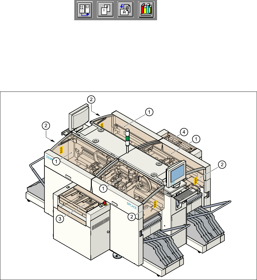
Fig. 2.2 - 1 Protective covers
2
The travelling range of the gantries is covered by four protective covers which can be folded up.
Side screens prevent access to the inside of the placement system from the side. The covers over
the input and output belts of the PCB conveyor and the guards on the input and output belts pre-
vent access to the PCB conveyor. 2
(1) Protective covers
(2) Safety screens
(3) Cover and guard on the input belt
(4) Cover and guard on the output belt
User Manual HS-50 2 Operational Safety
Software Version SR.501.xx 12/99 Issue US 2.2 Safety equipment
65
t IIt
Function
If one of the protective covers is folded up or one of the covers on the PCB conveyor is raised, the
power supply to the gantry axes will be interrupted immediately. The gantry axes will stop and the
message "Close the cover" will appear on screen. 2
Å Close the protective covers and press one of the Start buttons to continue placement.
2
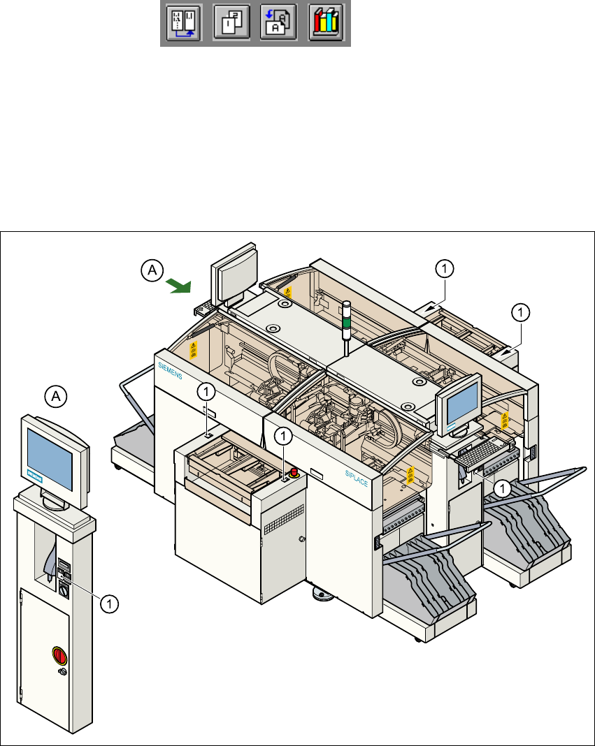
Fig. 2.2 - 2 Position of the Start buttons (white) on the placement system
(1)Start buttons (white) on the placement system
2