00191369-02.pdf - 第35页
User Manual HS-50 1 Introduction Software Version S R.501.xx 12/99 Issue US 1.11 Overview of the mod ules - controls 35 t I I t 1.1 1.2 Descripti on All the c ontrols can be reach ed by a 1.6 0 m tall p erson. 1 Main swi…
1 Introduction User Manual HS-50
1.11 Overview of the modules - controls Software Version SR.501.xx 12/99 Issue US
34
t IIt
1.11 Overview of the modules - controls
1.11.1 Controls
1
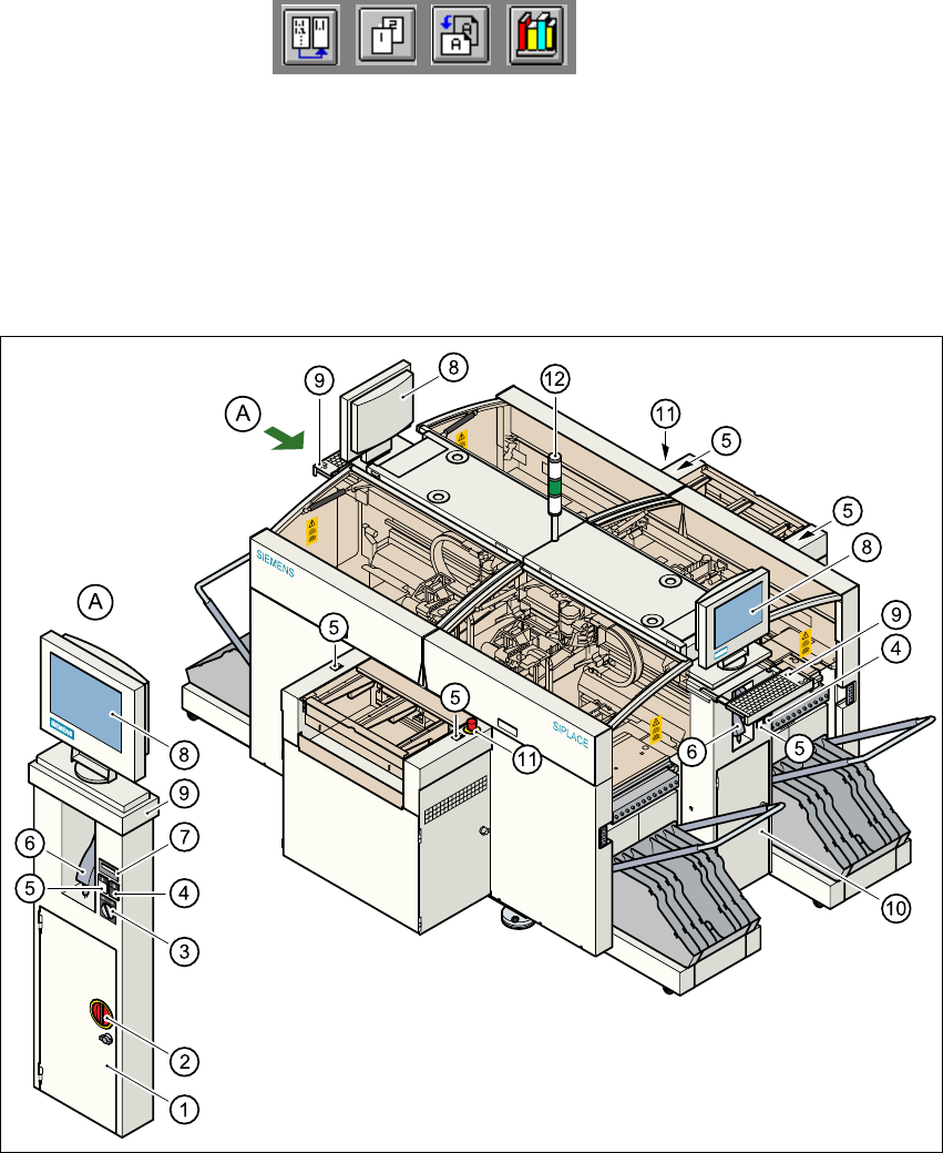
Fig. 1.11 - 1 Overview of the modules - controls
1
(1) Operating panel, left-hand side (2) Main switch
(3) Key switch (4) Stop button (black)
(5) Start button (white) (6) Component barcode scanner
(7) Component counter (8) LCD screen
(9) Keyboard with trackball (10) Operating panel, right-hand side
(11) Emergency stop mushroom-head push-button (12) Indicator lamps
User Manual HS-50 1 Introduction
Software Version SR.501.xx 12/99 Issue US 1.11 Overview of the modules - controls
35
t IIt
1.11.2 Description
All the controls can be reached by a 1.60 m tall person. 1
Main switch 1
The main switch is used to switch the power supply to the placement system on and off. 1
RISK OF DEATH
Some parts inside the placement system carry potentially lethal voltages - even when switched off
at the main switch. 1
Key switch 1
In normal mode, the key switch is set to "0". The key should be removed and kept in a safe place.
It must only be turned to position "I" (set-up mode) by authorized personnel, and then only for cer-
tain maintenance and servicing work. 1
Stop button 1
This button is used to stop the placement system. 1
Start button 1
This button starts the placement system after it has been switched on or after faults have been
eliminated. 1
Emergency stop mushroom-head push-button 1
The emergency stop mushroom-head push-button latches into place when it is pressed. The
power supply for the gantry axes, component tables, conveyor belts and cutting devices is inter-
rupted and the voltage to the star axes of the placement heads is reduced. The button must be
turned to release it. 1
Component counter 1
The component counter displays the number of components processed. 1
LCD screen 1
There is a flat LCD screen with a touch-sensitive surface (touch-screen) on either side of the
placement system. The screen resolution is 1024 x 768 pixels. 1
1 Introduction User Manual HS-50
1.11 Overview of the modules - controls Software Version SR.501.xx 12/99 Issue US
36
t IIt
Keyboard 1
A keyboard with the trackball is located beneath each screen. The keyboards can be pulled in and
out as required. 1
Indicator lamps 1
The sequence of colors is white - green - white. These lamps are used to signal operating statuses
and malfunctions of the placement system. 1
Component barcode reader 1
There is a compartment for a Datalogic DL 910 component barcode reader on either side of the
machine. The barcode reader enables the components to be set up and topped up quickly and
reliably. 1
1.11.3 Ergonomic arrangement of the controls
Figure 1.11 - 1 on page 34 provides an overview of the position of the controls, which are subdi-
vided into the following groups: 1
Operating panel on the right-hand side of the central console with 1
– LCD screen
– Keyboard with trackball
– Start button
– Component barcode reader
Operating panel on the left-hand side of the central console with 1
– LCD screen
– Keyboard with trackball
– Component counter
– Start button
– Stop button
–Key switch
– Component barcode reader
– Main switch
Input / output side of the PCB conveyor with 1
– Emergency stop mushroom-head push-buttons