00191369-02.pdf - 第66页
2 Operational Safety User Manual HS -50 2.2 Safety equipment Software Version SR.501.xx 12/99 Issue U S 66 t I I t 2.2.2 Guard on the input/o utput belt DANGER The guard mus t always be se t to the height of th e PCB to …
User Manual HS-50 2 Operational Safety
Software Version SR.501.xx 12/99 Issue US 2.2 Safety equipment
65
t IIt
Function
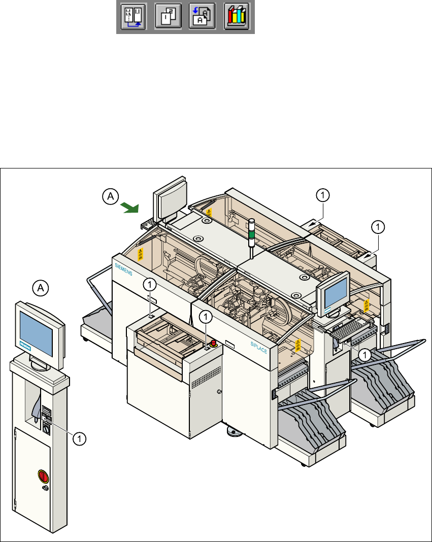
If one of the protective covers is folded up or one of the covers on the PCB conveyor is raised, the
power supply to the gantry axes will be interrupted immediately. The gantry axes will stop and the
message "Close the cover" will appear on screen. 2
Å Close the protective covers and press one of the Start buttons to continue placement.
2
Fig. 2.2 - 2 Position of the Start buttons (white) on the placement system
(1)Start buttons (white) on the placement system
2
2 Operational Safety User Manual HS-50
2.2 Safety equipment Software Version SR.501.xx 12/99 Issue US
66
t IIt
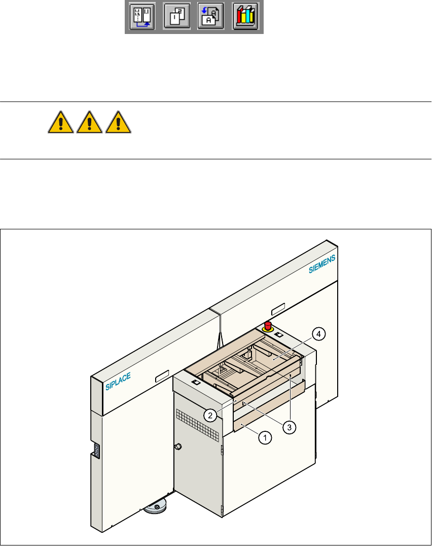
2.2.2 Guard on the input/output belt
DANGER The guard must always be set to the height of the PCB to be pro-
cessed. Ensure that the gap between the guard and the safety bar is as small as possible. 2
Guards are fitted on the input and output belts of the PCB conveyor. 2
Å Set the height of the guard using the slots so that the PCB can pass through.
2
Fig. 2.2 - 3 Guard on the input/output belt of the placement system
(1) Safety bar (fixed)
(2)Guard (adjustable)
(3) Slots for adjusting the height
(4) Cover
2
User Manual HS-50 2 Operational Safety
Software Version SR.501.xx 12/99 Issue US 2.2 Safety equipment
67
t IIt
2.2.3 Main switch, emergency stop mushroom-head push-buttons,
protective cover switches
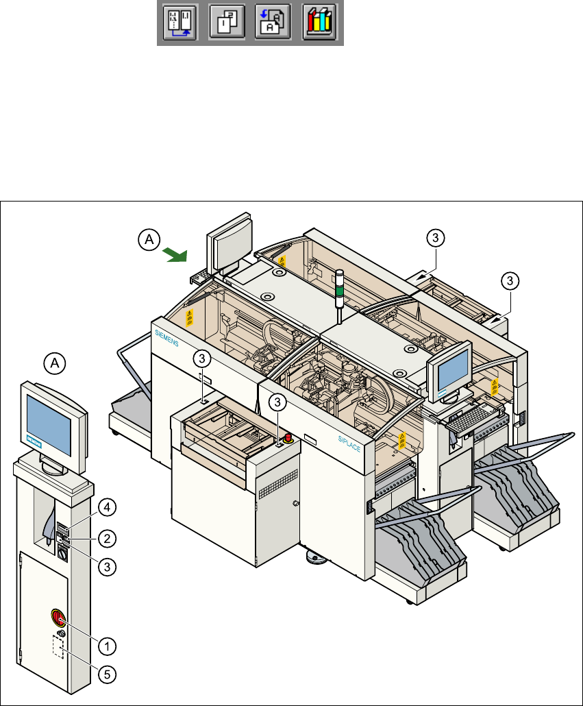
2.2.3.1 Position of main switch, start buttons etc. on the placement system
2
Fig. 2.2 - 4 Position of main switch, start buttons etc. on the placement system
(1)Main switch
(2)Stop buttons (black)
(3)Start buttons (white)
(4)Component counter
(5)Service socket in the power supply unit behind the safety doors
2