TK26714.PickHeightTeaching.pdf - 第5页
SMT Software Engineering Group IM Operations Y AMAHA MOTOR CO., L TD MDOC-SOFT50389 5/18 Fig 3.1 T each screen with Pick Height T eaching <Contents on the grid> Item Description Pick Height Pick height…

SMT Software Engineering Group
IM Operations YAMAHA MOTOR CO., LTD
MDOC-SOFT50389
4/18
3. Function Details
This function measures the height of a head above the target tape guide, and calculates its
appropriate pick height. The result can be applied to board data. Therefore, you don’t need
any special equipment such as a laser measuring instrument to measure the pick height.
A head moves down to the feeder tape guide, and the height is calculated based on its
vacuum level. The result is translated to pick height and displayed on the screen.
It is possible to apply the measured pick height to board data, and to use it in production.
There are two types of tape guide, iron and carbon. They have different measurement
positions, so that it is necessary to recognize a tape guide by the moving camera. However,
if you use only either type of tape guide feeders, you can skip the guide recognition. To
recognize a guide, the special mark data is necessary. For more details, please refer to
Chapter 4 or 6.
Teaching head is supposed to pick the first one of the target feeder parts. If the first head
can’t measure the height, the second head does. If no head can measure the height, a
measurement error occurs.
In V4.50STD_R1.000 or later, it is possible to measure the height without mount data as
long as fixed board data is read. In this case, mounting heads and nozzles are automatically
determined. Please note that the determined combination of heads and nozzles will be
different from that you want to set.
(▲1)
3.1 Using Method
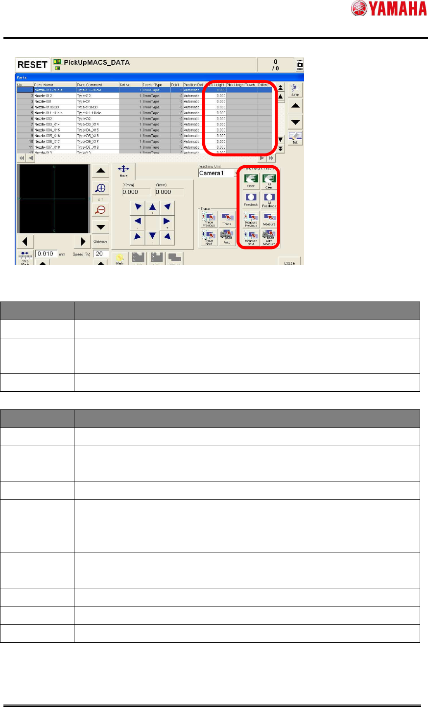
While this function is active, the [Parts] - [Teach] screen is displayed as below.
The contents marked in red are the added.
SMT Software Engineering Group
IM Operations YAMAHA MOTOR CO., LTD
MDOC-SOFT50389
5/18
Fig 3.1 Teach screen with Pick Height Teaching
<Contents on the grid>
Item Description
Pick Height
Pick height currently specified. You can edit this item directly.
Pick Height
Teach Result
Measured result of pick height. If measurement is failed or undone, this
item is shown with blank.
Difference
Difference between the original pick height and teaching height.
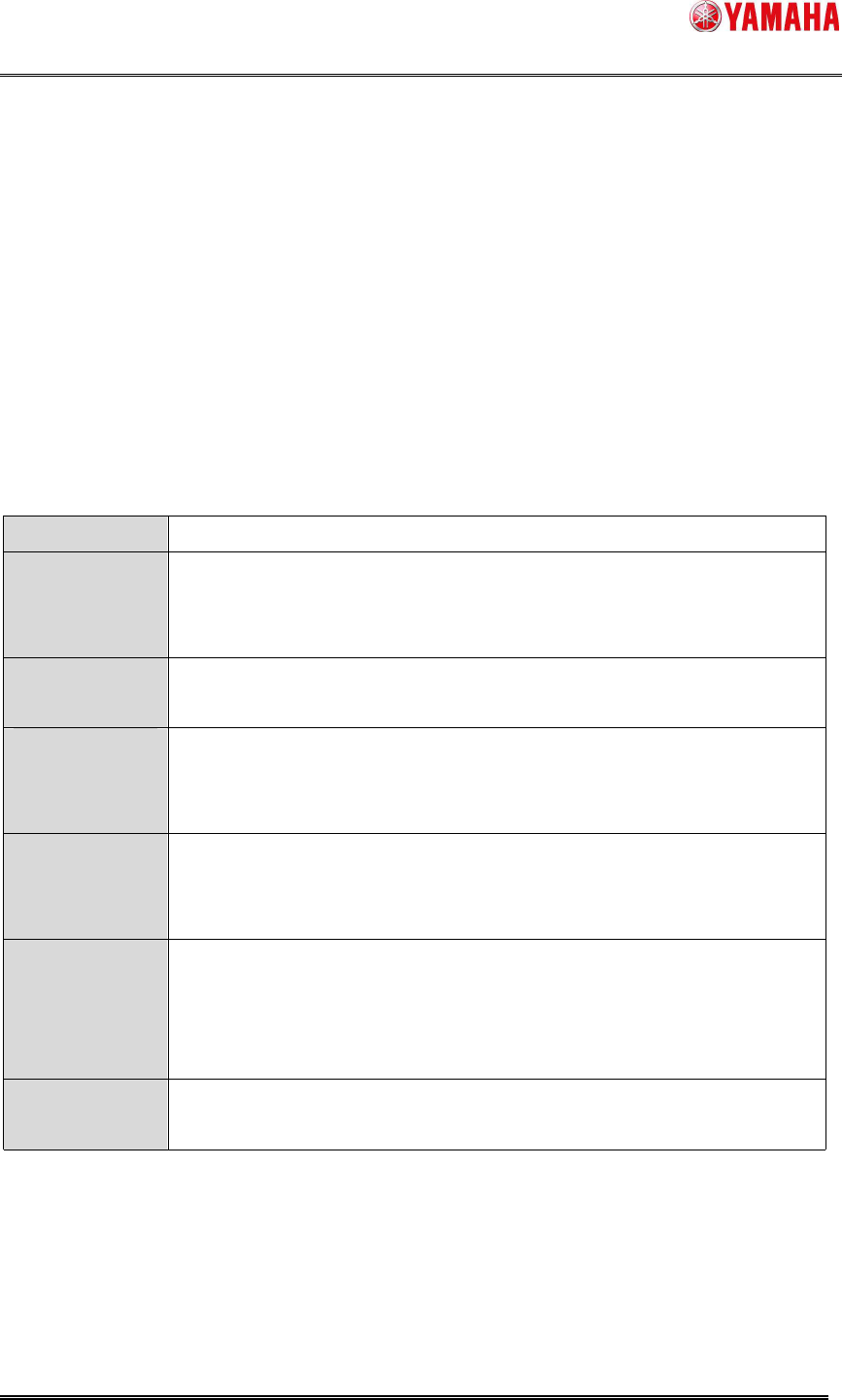
<Buttons on the right bottom>
Item Description
Measure
Pick height is measured for the parts selected on the grid.
Measure
Previous
Pick height is measured for the one before the selected parts on the grid.
Measure Next
Pick height is measured for the one next to the selected parts on the grid.
Auto Measure
When the [Measure Previous] or [Measure Next] button is pressed with
this button, pick height is measured for the next or previous parts in order
continuously.(Continuous teaching)
Feedback
When this button is pressed, teaching result is applied to pick height of the
selected parts.
All Feedback
All teaching results are applied to pick height of all parts.
Clear
Teaching result of selected parts is cleared.
All Clear
All teaching results are cleared.
< Caution >
- These items are grayed out when the feeder or nozzle of selected parts is unsupported.
At executing [Auto Measure], such feeders and nozzles are skipped.
SMT Software Engineering Group
IM Operations YAMAHA MOTOR CO., LTD
MDOC-SOFT50389
6/18
- Teaching results are maintained until board data is read.
< Note >
- Pick height teaching is performed one by one.
- It takes about 5 to 6 seconds per point.
3.2 Pick Height Take Over Function
When [TakeOver PickHeight] is enabled in the machine setting, “Pick Height” is taken over
to other board data, so that you don’t need to perform pick height teaching for every board
data.
To take over pick height, the target parts need to be used for production, or the board data
is saved after pick height feedback. Target pick height is written and read through a
takeover file at reading board data, or when the feeder is removed and attached.
File name
Feeder_(Feeder ID)@(Parts Name).sts
File contents ・Pick Height
* When the “Parts Data Auto Tuning” function is used, the tuning data is
also included.
Reading (take
over) timing
・When board data is read
・When feeder is attached
Take over
condition
・[Feeder ID] and [Parts Name] match
・Feeder is attached at reading board data.
・Writing conditions are not satisfied at attaching feeder.
Writing timing ・Before board data is read.
・Power OFF
・When the target feeder is removed
Writing
condition
・Some parts are mounted in auto-running.
or
・The [Feedback] button is pressed or [Pick Height] is edited, then the
board data is saved.
Delete timing
and condition
・When board data is read. (When server path is undefined, and takeover
files are over 2000, the older files are deleted.)
< Note >
・ File saving path is “D:¥Machine¥Status¥PartsTakeOver¥”, and can be changed on the
[Software Setting] – [Monitor] – [Parts Data Take Over] dialog.
・ When reading or writing of takeover file is failed, “Ea12994:
Failed to write parts data
take over file” or “Ea12995:
Failed to read parts data take over file” is recorded in the
error log.