00193897-0302_AI_MTC2+BE_DE+EN.pdf - 第140页
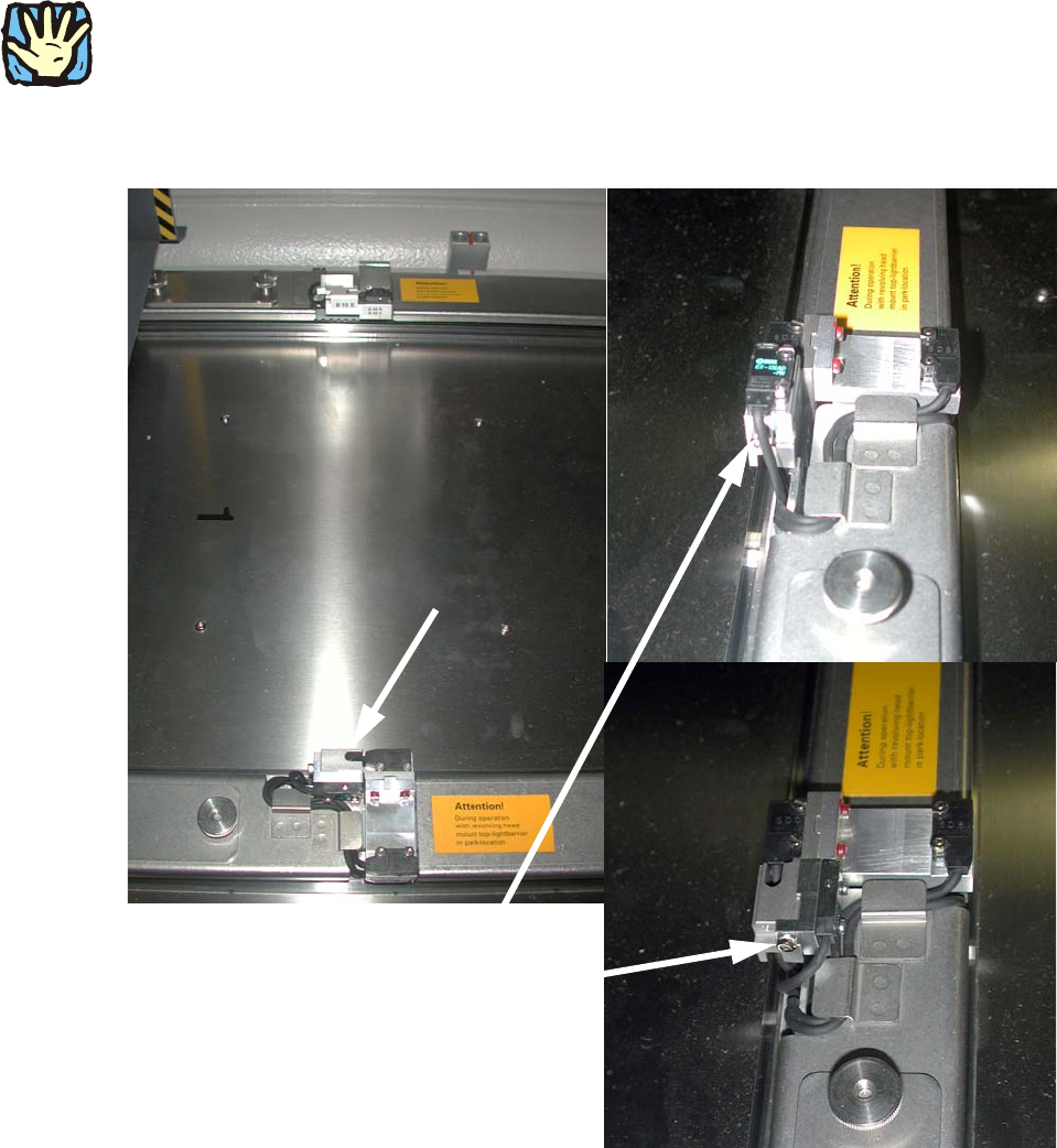
Assembly instructions MTC2 and Component docking unit on SIPLACE HF and X-se ries Edition 07/2009 138 2 Both the transmitter and receive r must be mounted in the parked position. 2 2 : Fix the light barrier in the p arke…
Assembly instructions MTC2 and Component docking unit on SIPLACE HF and X-series
Edition 07/2009
137
2.13.1 Conversion of light barriers MTC2 in combination with a C&P 6/12 / CPP
2
Crash risk: If an MTC2 is operated in a location or placement area with C&P6/12, the top light
barrier must be brought into the parked position for high components, otherwise there is a risk of
a head crash. 2
: Loosen the screw on the top light barrier (transmitter and receiver) on tower 1.
Light barrier:
prior to modification and
mounted in parked position
2
Fig. 2.13.1 Top light barrier on MTC2
2
2
Assembly instructions MTC2 and Component docking unit on SIPLACE HF and X-series
Edition 07/2009
138
2
Both the transmitter and receiver must be mounted in the parked position.
2
2
: Fix the light barrier in the parked position.
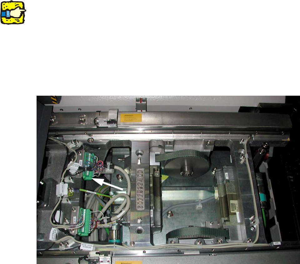
: Remove the plate over the connectors on tower 1.
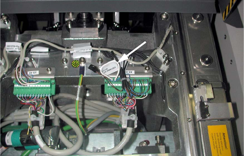
: Remove the contacts 13 (brown) and 14 (black) on connector XS43.
: Insulate both cable ends.
2
Fig. 2.13.2 Stecker X43
2
2
2
2
2
2
2
2
2
Assembly instructions MTC2 and Component docking unit on SIPLACE HF and X-series
Edition 07/2009
139
: Connect both contacts to the cable bridge (03014445-).
2
Fig. 2.13.3 Connector X43 with cable bridge on 13+14
: Refit the plate over the connectors.
2.13.2 Final work relating to MTC2
: Connect the power supply for the MTC2 and machine.
: Configure the "new" machine in the station editor of SIPLACE Pro as well as under SITEST on
the st
ation computer.
2
: Switch on the machine at the main switch.
: Close the covers.
: Carry out referencing.
: Change to SITEST.
: Calibrate the masks on MTC2.
: Copy the data of the MTC to the machine database of the placement station and if necessary
ba
cku
p the data on a data storage medium.