00198368-01_UM_SIPLACESX12-DockingStation_DE_EN_ZH.pdf - 第45页
User manual Docking station for SIPLACE SX component trolleys 1 Introduction Edition 02/2018 1.1 Overview 45 1 Introduction This user manual is a guide or refe rence work for opera ting and setting up the SIPLACE ® docki…

All names identified by ® are registered trademarks of ASM Assembly Systems GmbH & Co. KG. The remaining trademarks in this publication
may be trademarks whose use by third parties for their own purposes could violate the rights of the owner.
We have reviewed the contents of this publication to ensure consistency with the hardware and software described. Since variance cannot be
precluded entirely, we cannot guarantee full consistency.
However, the information given in this publication is reviewed regularly and any necessary corrections are included in subsequent editions.
This is the original user manual.
Copyright © ASM Assembly Systems Technical data subject to change
ASM Assembly Systems GmbH&Co.KG
Rupert-Mayer-Str. 44
81379 Munich
Germany
www.asm-smt.com
Item no.:00198368-01
Printed by ASM Assembly Systems
User manual Docking station for SIPLACE SX component trolleys 1 Introduction
Edition 02/2018 1.1 Overview
45
1 Introduction
This user manual is a guide or reference work for operating and setting up the SIPLACE
®
docking
station for SIPLACE SX1/SX2 component trolleys.
1.1 Overview
The docking station is an additional unit for the pre-setup area and serves as a link between the
pre-setup area and the SIPLACE SX/SX2 component trolleys. It allows the component trolleys to
be set up externally with feeder modules, function tests and setup verification.
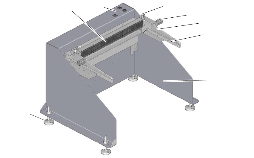
1
Fig. 1.1 - 1 Docking station for SIPLACE SX
1
(1) Docking station (5) Sensor for component trolley detection
(2) COT insert for SX1/SX2 (6) Controls
(3) Sliding rails for guiding and docking the
changeover table
(7) EDIF (energy and data interface)
(4) Pneumatic cylinder for locking the compo-
nent trolley
(8) Height-adjustable feet for fixture to the un-
derlying surface.
1
5
3
2
4
7
8
6
1 Introduction User manual Docking station for SIPLACE SX component trolleys
1.2 Docking station serial number Edition 02/2018
46
The main tasks performed by the docking station are as follows:
– Supply of energy to the component trolley and X feeder modules
– Provision of an infrastructure for communication between the pre-setup location PC and the
feeder modules
With the help of the docking station, the operator can perform function tests to the X feeder mod-
ules outside the production environment and can check the setup. There are two rows, each with
four docking stations, connected via the CAN bus of the pre-setup PC. Each docking station has
its own power and compressed air connection.
The COT insert for the docking station can be adjusted to the required PCB conveyor height. The
component trolley is pushed into the docking station for the pre-setup process. The component
trolley slides along the COT insert rails with the roller bearings on its sides, asm far as the energy
and data interface connection. The EDIF in the COT insert unit is positioned precisely in relation
to the changeover table with the feeder module EDIF.
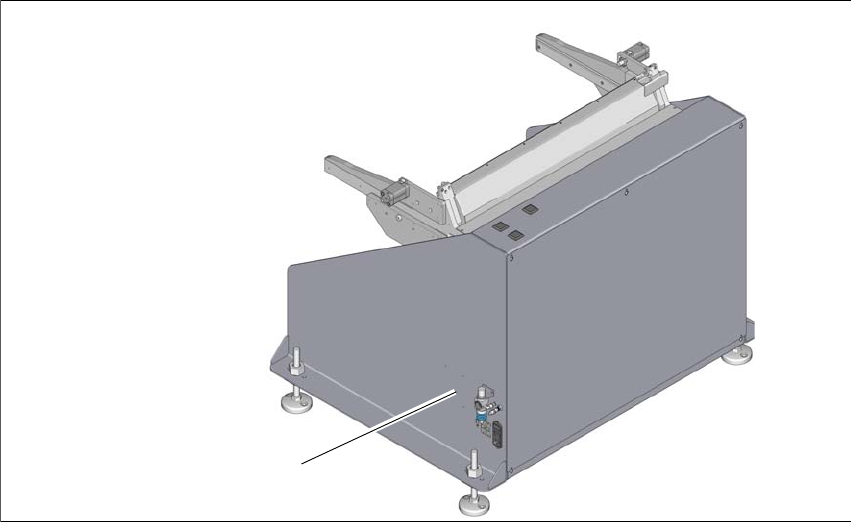
1.2 Docking station serial number
The docking station serial number is located on the typeplate.
1
Fig. 1.2 - 1 Position of typeplate
(1) Typeplate
(1)