00198368-01_UM_SIPLACESX12-DockingStation_DE_EN_ZH.pdf - 第68页
3 Product description User manual Docking sta tion for SIPLACE SX component trolleys 3.3 Assembly and fixtures Edition 02/2018 68
User manual Docking station for SIPLACE SX component trolleys 3 Product description
Edition 02/2018 3.3 Assembly and fixtures
67
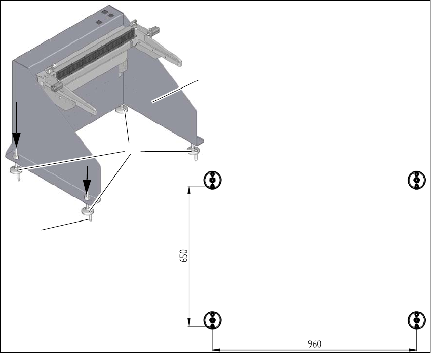
3.3.2 Assembly
The docking station is fixed to the floor with four heavy-duty anchors TA M, ∅12mm and the other
fixtures.
3
Fig. 3.3 - 2 Fixtures and hole drilling pattern
(1) Set the docking station (1) up where it is to be installed and align it accordingly.
(2) Align the base feet (2) so that the holes in them match the holes in the metal plate above.
(3) Mark the front hole of each base foot with a pencil or suitable tool.
(4) Place the docking station to one side.
(5) Drill the four holes with a diameter of 12mm and a depth of 80mm.
(6) Insert the heavy-duty anchors (3) into the drilled holes.
(7) Move the docking station back to its place and fasten with the screws provided.
1
3
2
3 Product description User manual Docking station for SIPLACE SX component trolleys
3.3 Assembly and fixtures Edition 02/2018
68
User manual Docking station for SIPLACE SX component trolleys 4 Operation
Edition 02/2018 4.1 Controls and displays
69
4 Operation
4.1 Controls and displays
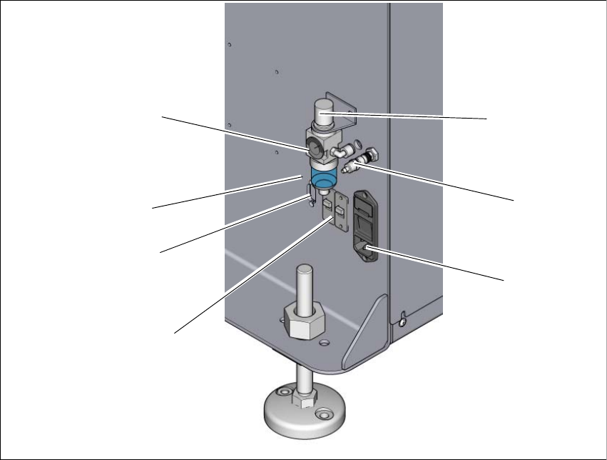
4.1.1 Pneumatic unit and connections
4
Fig. 4.1 - 1 Docking station - pneumatic unit and connections
(1) Rotary knob for setting the operating pressure
(2) Compressed air connection
(3) Mains switch and mains connection
(4) Switch S1 and S2 for setting the CAN bus address
(5) CAN bus connection
(6) Label with diagram of switch S1 and S2 for addressing the CAN bus
(7) Manometer for showing operating pressure
2
1
7
3
4
5
6