00198368-01_UM_SIPLACESX12-DockingStation_DE_EN_ZH.pdf - 第73页
User manual Docking station for SIPLACE SX component trolleys 4 Operation Edition 02/2018 4.3 Docking and undocking the component trolley 73 4.3 Docking and undocking the component trolley 4 Fig. 4.3 - 1 Docking station …
4 Operation User manual Docking station for SIPLACE SX component trolleys
4.2 Adjusting the conveyor height Edition 02/2018
72
To set the conveyor height, proceed as follows:
Loosen the locknuts on all base feet.
Use the adjusting screws to set the size Y (see table).
Check whether the machine is horizontally level.
4
Machine height Size X Size Y Size Z
900mm 859mm 100mm 770mm
930mm 889mm 130mm 800mm
950 mm 909mm 150mm 820mm
User manual Docking station for SIPLACE SX component trolleys 4 Operation
Edition 02/2018 4.3 Docking and undocking the component trolley
73
4.3 Docking and undocking the component trolley
4
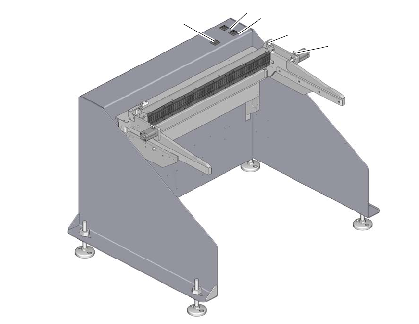
Fig. 4.3 - 1 Docking station
(1) Locking and unlocking of feeder modules (green button)
(2) Component trolley unlocking function (white button)
(3) Pneumatic cylinder for locking the component trolley
(4) Sensor for component trolley detection
(5) Feeder module tear down (black button)
2
1
3
4
5
4 Operation User manual Docking station for SIPLACE SX component trolleys
4.3 Docking and undocking the component trolley Edition 02/2018
74
4.3.1 Docking the SIPLACE SX component trolley onto the docking station
4
Push the component trolley into the docking station, until it is locked by the pneumatic cylin-
der.
– The green button (item 3 in fig. 4.1 - 1
, page 69) and the white button (item 2 in fig. 4.1 - 1,
page 69
) will flash briefly. Once the component trolley is locked into place properly, the white
button will shine continuously (component trolley unlocking function).
– If the component trolley is not properly locked into place, the white button will flash.
– If the feeder modules are locked into place properly, the green button will shine.
4.3.2 Undocking the SIPLACE SX component trolley from the docking station
4
In order to unlock the component trolley, the feeder modules must be locked into place.
Make sure that the green button (item 3 in fig. 4.1 - 1
, page 69) shines.
Press the white button (item 2 in fig. 4.1 - 1, page 69 ). The component trolley will be released.
Pull the component trolley back and out of the docking station.
WARNING
Risk of injury to hands!
While docking, do not reach into the areas between component trolley and docking sta-
tion.
WARNING
Risk of injury to hands!
While docking, do not reach into the areas between component trolley and docking sta-
tion.