00198368-01_UM_SIPLACESX12-DockingStation_DE_EN_ZH.pdf - 第65页
User manual Docking station for SIPLACE SX component trolleys 3 Product description Edition 02/2018 3.2 Transportation locks 65 3.2 T ransport ation locks After unp acking and before initial operation, remove the shipp i…
3 Product description User manual Docking station for SIPLACE SX component trolleys
3.1 Overview Edition 02/2018
64
3.1.1 Technical data
3
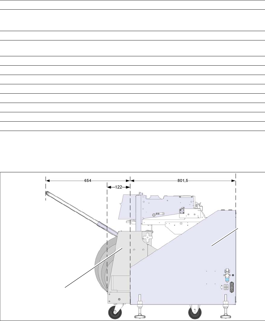
3.1.2 Dimensions with docked component trolley
3
Fig. 3.1 - 2 Docking station with docked component trolley - dimensions in millimeters
(1) Component trolley
(2) Docking station
Length x width 801.5mm x 1038mm
Height (to centering pin) 859 mm for 900 mm PCB conveyor height
889 mm for 930 mm PCB conveyor height
909 mm for 950 mm PCB conveyor height
Weight 105kg
Compressed air pressure values p
min
0.5MPa (5.0bar)
p
max
1.0MPa (10.0bar)
Compressed air connection Connection plug KS 2-M5-A
Flow through 5Nl/min
*a
*)a Under normal atmospheric conditions at 20°C and 1013 hPa
Supply voltage 88 - 264 V~
Number of wires/phases 3 / 1
Frequency max. 63 Hz
Rated current max. 2 A
Performance 0.23 kW
Fuse 2 x 8A
1
2
User manual Docking station for SIPLACE SX component trolleys 3 Product description
Edition 02/2018 3.2 Transportation locks
65
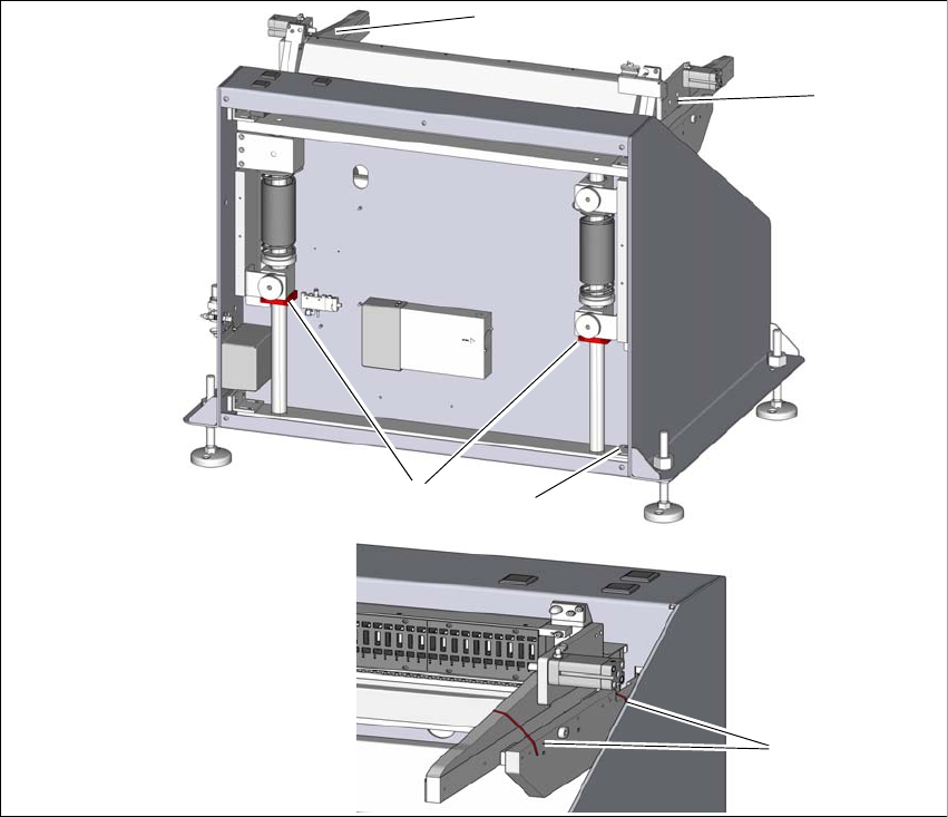
3.2 Transportation locks
After unpacking and before initial operation, remove the shipping braces from the docking station.
3
Fig. 3.2 - 1 Shipping braces
(1) Two shipping braces on the lifting axis
(2) Storage place for the shipping braces item 1
(3) Four shipping braces for the sides
To loosen the shipping braces (1), remove the back cover. Loosen the shipping braces (1)
and fasten these loosely at the storage place (3).
Fit the cover.
The sides are secured with two cable ties (3) each. To remove the shipping brace (2), use a
suitable tool to cut the four red cable ties.
1
2
3
3
3
3 Product description User manual Docking station for SIPLACE SX component trolleys
3.3 Assembly and fixtures Edition 02/2018
66
3.3 Assembly and fixtures
To guarantee safe and reliable operation of the docking station, make sure that the docking station
is screwed to the floor with the assembly kit provided.
3.3.1 Assembly equipment
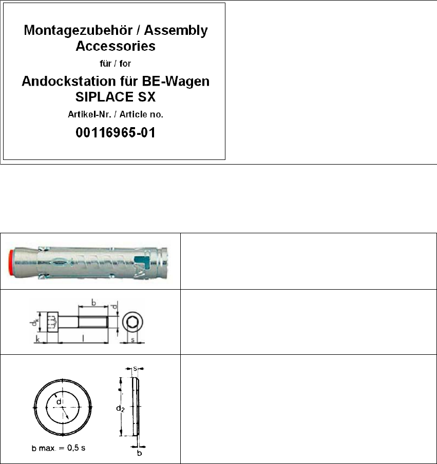
The assembly equipment is provided in a separate package. This package is marked with the fol-
lowing label.
3
Fig. 3.3 - 1 Assembly equipment
3.3.1.1 Fixtures
3
Contents:
(1) Mains power cable
(2) Fixtures
3
4x heavy-duty anchors TA M, ∅12 mm
3
4x cylinder screws, DIN EN ISO 4762 M8x80-8.8
3
4x disc, DIN EN ISO 7090 8.4-140HV