00198368-01_UM_SIPLACESX12-DockingStation_DE_EN_ZH.pdf - 第66页
3 Product description User manual Docking sta tion for SIPLACE SX component trolleys 3.3 Assembly and fixtures Edition 02/2018 66 3.3 Assembly and fixtures T o guarantee safe and reliable operation of the do cking statio…
User manual Docking station for SIPLACE SX component trolleys 3 Product description
Edition 02/2018 3.2 Transportation locks
65
3.2 Transportation locks
After unpacking and before initial operation, remove the shipping braces from the docking station.
3
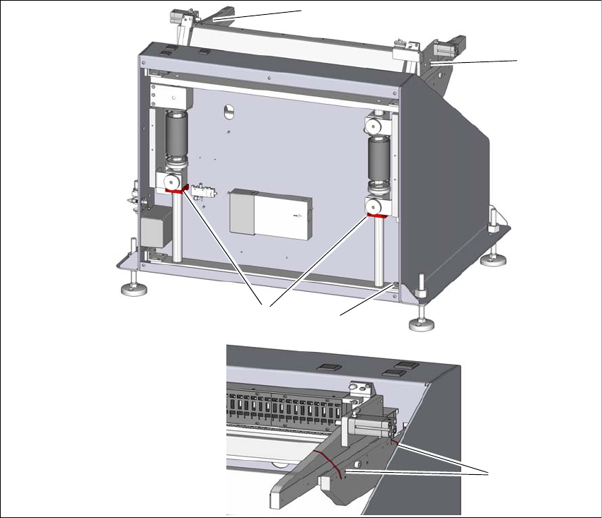
Fig. 3.2 - 1 Shipping braces
(1) Two shipping braces on the lifting axis
(2) Storage place for the shipping braces item 1
(3) Four shipping braces for the sides
To loosen the shipping braces (1), remove the back cover. Loosen the shipping braces (1)
and fasten these loosely at the storage place (3).
Fit the cover.
The sides are secured with two cable ties (3) each. To remove the shipping brace (2), use a
suitable tool to cut the four red cable ties.
1
2
3
3
3
3 Product description User manual Docking station for SIPLACE SX component trolleys
3.3 Assembly and fixtures Edition 02/2018
66
3.3 Assembly and fixtures
To guarantee safe and reliable operation of the docking station, make sure that the docking station
is screwed to the floor with the assembly kit provided.
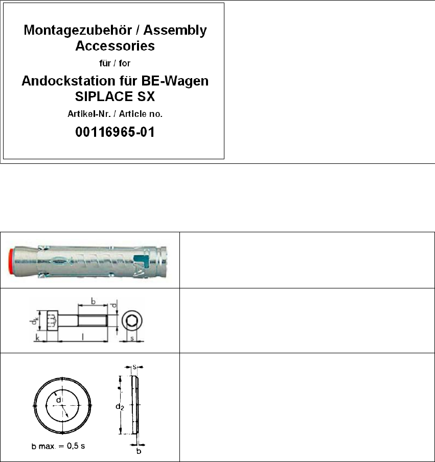
3.3.1 Assembly equipment
The assembly equipment is provided in a separate package. This package is marked with the fol-
lowing label.
3
Fig. 3.3 - 1 Assembly equipment
3.3.1.1 Fixtures
3
Contents:
(1) Mains power cable
(2) Fixtures
3
4x heavy-duty anchors TA M, ∅12 mm
3
4x cylinder screws, DIN EN ISO 4762 M8x80-8.8
3
4x disc, DIN EN ISO 7090 8.4-140HV
User manual Docking station for SIPLACE SX component trolleys 3 Product description
Edition 02/2018 3.3 Assembly and fixtures
67
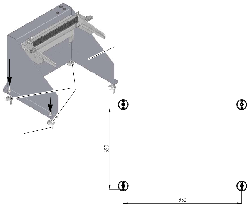
3.3.2 Assembly
The docking station is fixed to the floor with four heavy-duty anchors TA M, ∅12mm and the other
fixtures.
3
Fig. 3.3 - 2 Fixtures and hole drilling pattern
(1) Set the docking station (1) up where it is to be installed and align it accordingly.
(2) Align the base feet (2) so that the holes in them match the holes in the metal plate above.
(3) Mark the front hole of each base foot with a pencil or suitable tool.
(4) Place the docking station to one side.
(5) Drill the four holes with a diameter of 12mm and a depth of 80mm.
(6) Insert the heavy-duty anchors (3) into the drilled holes.
(7) Move the docking station back to its place and fasten with the screws provided.
1
3
2