Galaxy EX Safety Features.pdf - 第11页
SA FETY FEA TU RES HI GH VOLTAGE PRO TECTIO N Ch apte r Is sue 6, Jun 18 Tech ni cal R efer enc e Manual 2. 11 HIGH VO L T AG E P ROTE C TI ON Ac ce ss Whe re inco m ing supp ly v olta ges are p re se nt, prot ect ion is…

SAFETY FEATURES
PRINTHEAD COVER
2.10 Technical Reference Manual Chapter Issue 6, Jun 18
PRINTHEAD COVER
Raising the printhead cover allows access to the following areas:
• Printhead
• Paste Dispenser
• Squeegee/ProFlow
• Stencil/Screen
• Under Screen Cleaner
•Tooling
The printhead cover is accessible to the operator and a cam interlock safety
switch protects personnel from the mechanisms during normal line operations.
Raising the printhead cover renders the following areas of the machine
inactive:
• Lid Bolt
• Moving Rail Stepper
• Print Carriage Servo (axis stopped before power is removed)
• Paste Cartridge Tilt Up/Tilt Down Pneumatic Actuator
• Paste Dispense Solenoid and Stepper Motor
• Rail System Front and Rear Belt Motor Drives
• Rising Table Brake (brake engages when power is cut)
• Rising Table Servo
• Squeegee/ProFlow Stepper Motor(s)
• System Lamp
• Underscreen Cleaner Paper Feed Motor
• Underscreen Cleaner Solvent Pump
• Underscreen Cleaner Squeegee Solenoid
• Vacuum Tooling Solenoid
• X Camera Motor (axis stopped before power is removed)
• X Forward, X Rear and Y Chase Alignment Stepper Motors
• Y Camera Motor (axis stopped before power is removed)
Recovery Close the printhead cover. When prompted by a screen message press the
System button. This enables resumption of operations, where allowed by the
control system.
SAFETY FEATURES
HIGH VOLTAGE PROTECTION
Chapter Issue 6, Jun 18 Technical Reference Manual 2.11
HIGH VOLTAGE PROTECTION
Access Where incoming supply voltages are present, protection is afforded by
controlling access to the enclosures that house the supply. The machine is
fitted with a mains isolator switch that cuts power to all circuits located beyond
the switch.
Hazard Warning
Labels
Hazard warning labels are placed on the outside of enclosures where
dangerous voltage (100V-240V) terminations are present within.
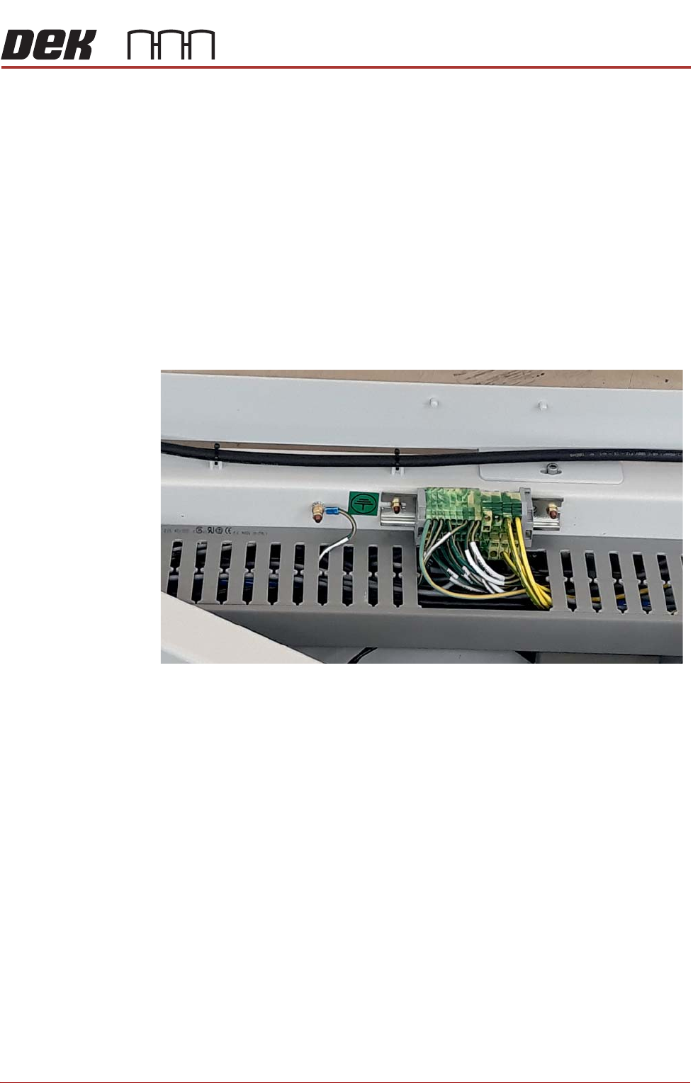
Earth Bonding All external metal surfaces are mechanically and electrically bonded to the
printer’s earth point. The bonding wire used is identified by its green and
yellow insulation and is commonly used to earth bond throughout. Care should
be taken when removing these links that when they are replaced they are
secured tightly and cleanly.
SAFETY FEATURES
HIGH VOLTAGE PROTECTION
2.12 Technical Reference Manual Chapter Issue 6, Jun 18
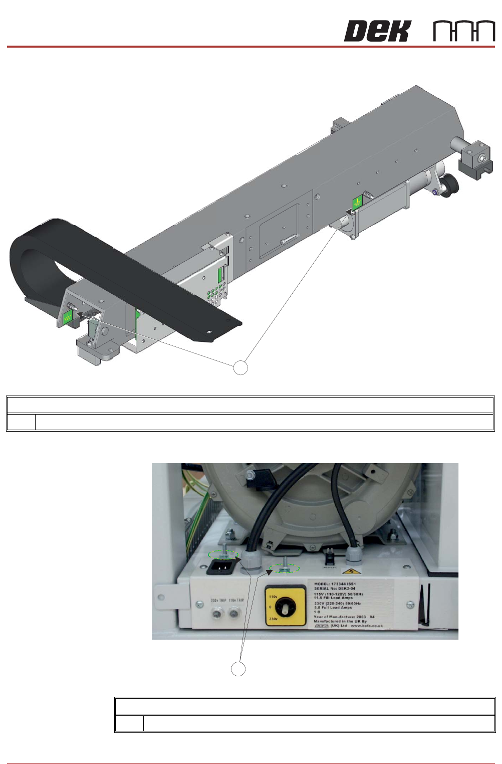
Earth Studs and Labels on the Print Carriage
1 Earth Studs and Labels
Earth Studs and Labels on the Vacuum Pump
1 Earth Studs and Labels