User Manual E-by-SIPLACE 用户手册.pdf - 第159页
User manual E by SIPLACE 3 Technical data and assemblies From software version SC 712.1 Edition 05/2019 3.10 Changeover t able for E by SIPLACE 159 3 Fig. 3.10 - 2 Changeover table, E by SIPLACE (1) Changeover table with…
3 Technical data and assemblies User manual E by SIPLACE
3.10 Changeover table for E by SIPLACE From software version SC 712.1 Edition 05/2019
158
3.10 Changeover table for E by SIPLACE
Item no. 03104678-xx Changeover table for E by SIPLACE with 60 tracks
The changeover tables are stand-alone modules that can be set up with
SIPLACE SmartFeeder E.
3
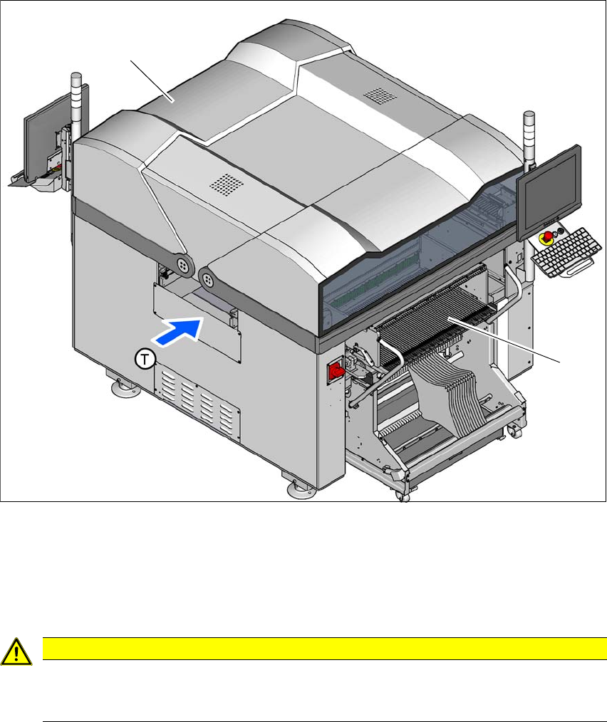
Fig. 3.10 - 1 Changeover table locations, E by SIPLACE (Example - double sided machine)
(1) Location 1
(2) Location 2
(T) Direction of PCB transport
3
CAUTION
The E by SIPLACE changeover tables may only be docked onto locations at which the
changeover table COT insert for the E by SIPLACE has been installed
(fig. 5.16 - 3, page 253 ).
(1)
(2)
User manual E by SIPLACE 3 Technical data and assemblies
From software version SC 712.1 Edition 05/2019 3.10 Changeover table for E by SIPLACE
159
3
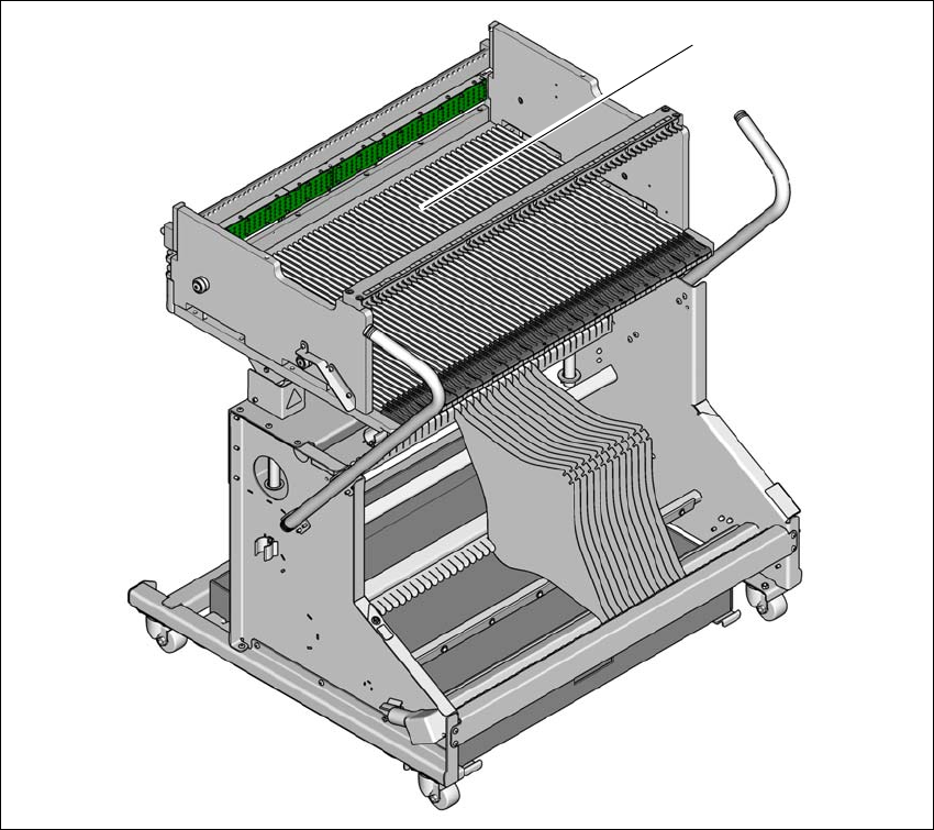
Fig. 3.10 - 2 Changeover table, E by SIPLACE
(1) Changeover table with 60 tracks
(1)
3 Technical data and assemblies User manual E by SIPLACE
3.10 Changeover table for E by SIPLACE From software version SC 712.1 Edition 05/2019
160
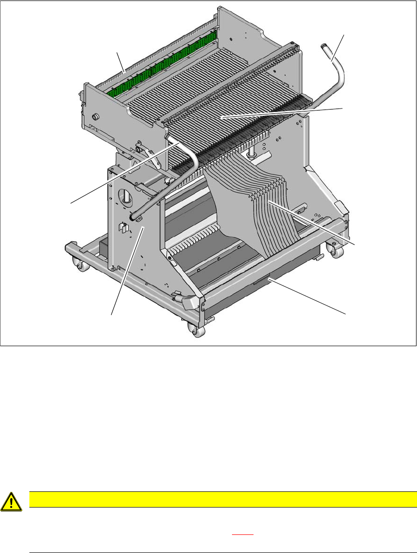
3.10.1 Structure
The changeover table essentially consists of the chassis, the changeover table for holding the
feeder modules, the tape reel container and the waste tape container.
3
Fig. 3.10 - 3 Changeover table, E by SIPLACE with 60 tracks - overview
(1) Chassis
(2) Changeover table
(3) Tape container
(4) Waste tape container
(5) Handle
(6) Centering bar
3
CAUTION
Observe the safety instructions!
Observe the safety instructions in section 5.9.2, page 228 when you pull the tape re-
ject bin out of the changeover table.
(1)
(2)
(5)
(4)
(3)
(6)
(5)