JUKI FX-3R MAINTENANCE GUIDE.pdf - 第23页
FX-3R Maintenance Guide 2-5 SV support A SL6030692TN × 4 pcs. Solenoid valve Head cover SL6030692TN × 2 pcs. Head unit SL6052092TN × 6 pcs. XM base Rev. 1.00
FX-3R Maintenance Guide
2-4
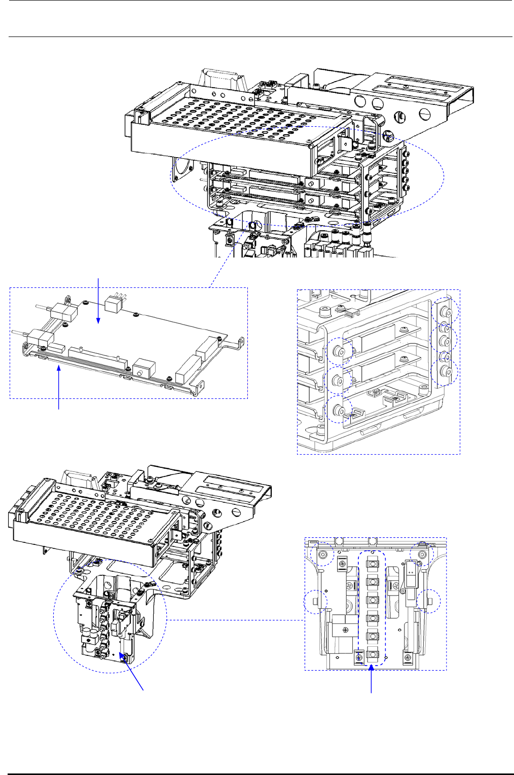
ZT-driver board
ZT-driver support
Right side (Same as the left side)
SL6041492TN
×
6 pcs. (one side)
Z-power connector base
SL6040892TN × 4 pcs.
Z-motor power cable
Rev. 1.00
FX-3R Maintenance Guide
2-5
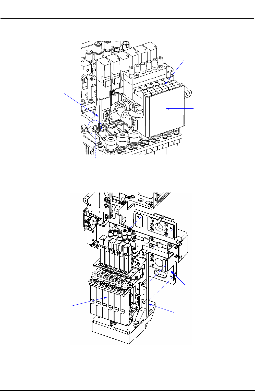
SV support A
SL6030692TN
×
4 pcs.
Solenoid valve
Head cover
SL6030692TN × 2 pcs.
Head unit
SL6052092TN × 6 pcs.
XM base
Rev. 1.00
FX-3R Maintenance Guide
2-6
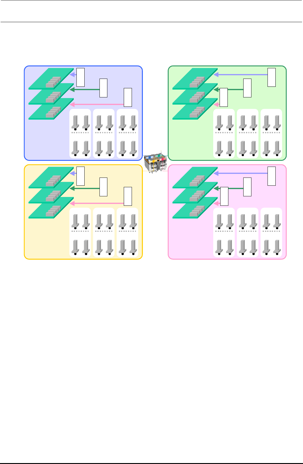
[Connection destinations of θ-motor cable connectors to be connected to ZT-driver PCB]
∗ Each connector is described by relevant head No.
LR
Axis 1
Axis 2
Axis 3
Axis 4
θ5 θ6
Z5 Z6
θ3 θ4
Z3 Z4
θ1 θ2
Z1 Z2
θ1
Z1
θ2
Z2
θ3
Z3
θ4
Z4
θ5
Z5
θ6
Z6
LF
Axis 1
Axis 2
Axis 3
Axis 4
θ5 θ6
Z5 Z6
θ3 θ4
Z3 Z4
θ1 θ2
Z1 Z2
θ2
Z2
θ1
Z1
θ4
Z4
θ3
Z3
θ6
Z6
θ5
Z5
RR
Axis 1
Axis 2
Axis 3
Axis 4
θ5 θ6
Z5 Z6
θ3 θ4
Z3 Z4
θ1 θ2
Z1 Z2
θ5
Z5
θ6
Z6
θ1
Z1
θ2
Z2
θ3
Z3
θ4
Z4
RF
Axis 1
Axis 2
Axis 3
Axis 4
θ5 θ6
Z5 Z6
θ3 θ4
Z3 Z4
θ1 θ2
Z1 Z2
θ2
Z2
θ1
Z1
θ4
Z4
θ3
Z3
θ6
Z6
θ5
Z5
∗ Connect the θ-motor power cables and θ-motor encoder cables while referring to the Figure
below.
Figure 2-1-1 Z/θ-Driver and Motor Layout Relationship Diagram
When Viewed from Software
Rev. 1.00