JUKI FX-3R MAINTENANCE GUIDE.pdf - 第56页
FX-3R Maintenance Guide 5-3 Rev. 1.00 5-3. Replacing the STATION, IN, OUT, and JOINT Motors 1) Disconnect the connector of the motor relay cable. 2) Loosen the screws f fixing the motor bracket d to detach the drive belt…
FX-3R Maintenance Guide
5-2
Rev. 1.00
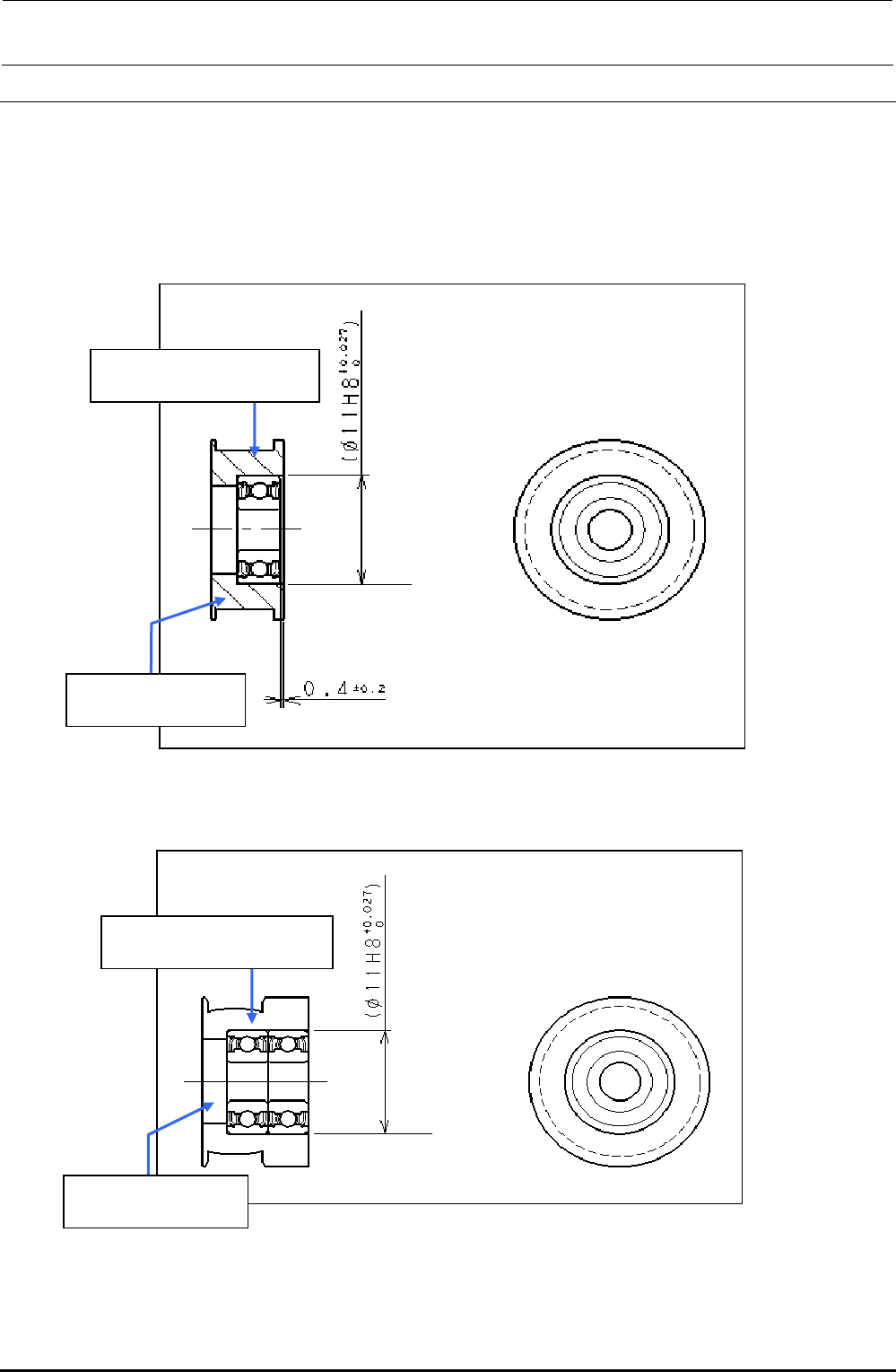
5-2. Replacing the Transport Pulley
Two kinds of transport pulleys are available. If the mounting position is changed or the pulley is
mounted incorrectly, this may cause incorrect pulley rotation or incorrect alignment of the transport
belt, resulting in wear on the belt.
Always refer to relevant mounting procedure when mounting the transport pulley.
5-2-1. Transport Pulley A Assembly: E21117150A0
Figure 5-2-1-1 Transport Pulley A Assembly
5-2-2. Transport Pulley B Assembly: E20897210A0
Figure 5-2-2-1 Transport Pulley B Assembly
SB104000100
Roll bearing Q’ty: 1
E2111715000
Transport pulley A Q’ty: 1
E2089721000
Transport pulley B Q’ty: 1
SB104000100
Roll bearing Q’ty: 2
FX-3R Maintenance Guide
5-3
Rev. 1.00
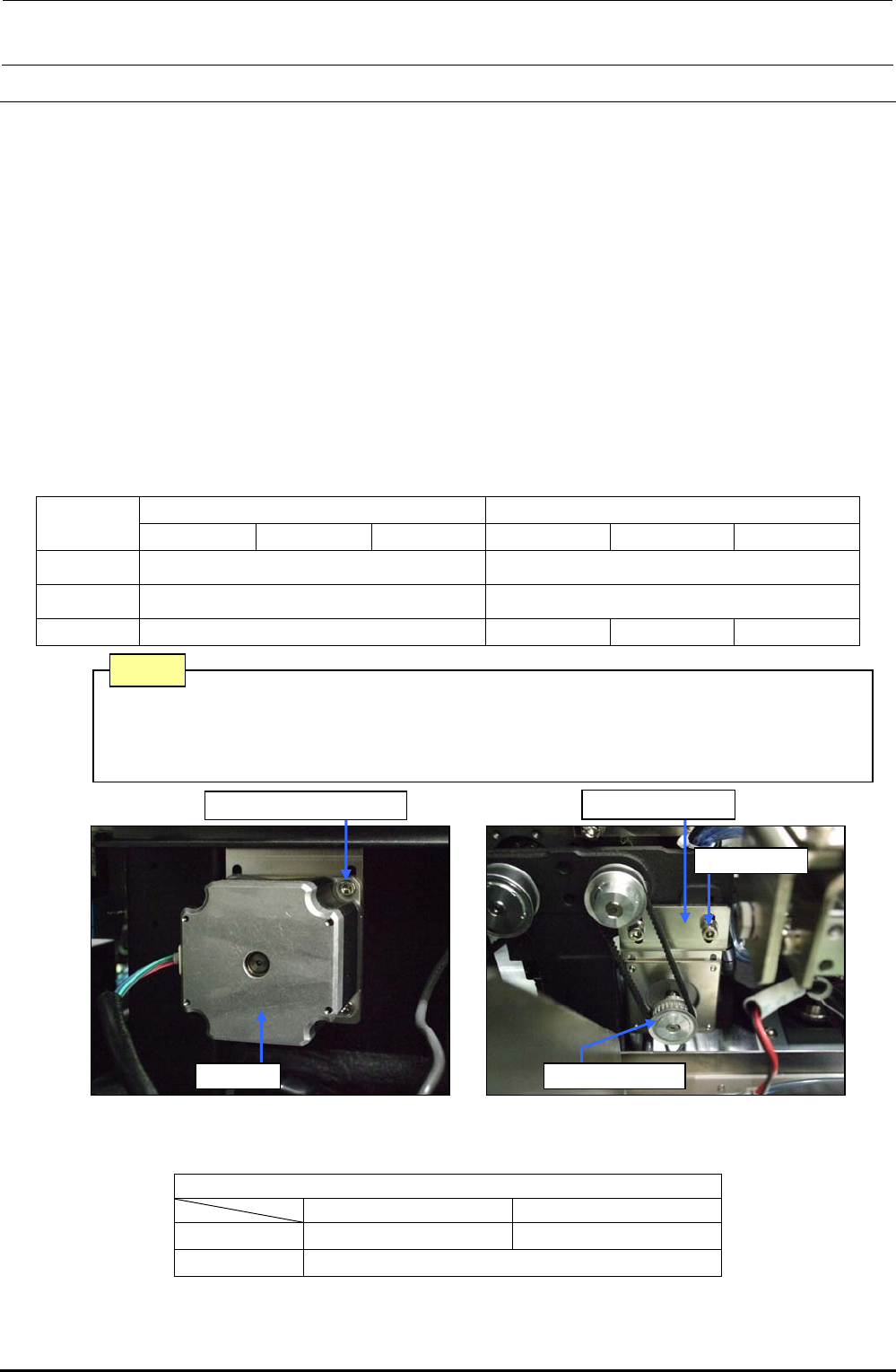
5-3. Replacing the STATION, IN, OUT, and JOINT Motors
1) Disconnect the connector of the motor relay cable.
2) Loosen the screws f fixing the motor bracket d to detach the drive belt from the motor pulley
e.
3) Loosen the motor fixing screws g and detach the motor c.
Reassemble the parts and components in the reverse order of disassembly. (i.e. from step 3) to step
1)). While reassembling, the following adjustment is required.
<Adjustment> For details, see “PWB Transport” in the QA table.
1) The end face of the motor pulley shall be aligned with the end of the motor shaft.
2) Tension adjustment of the timing belt
• Specification value: 17.5 to 21.5N⋅m
Use UNITTA's acoustic belt tension meter for measurement. Enter the following values
to the tension meter and make a measurement:
Table 5-3-1 Transport Motor Tension Adjustment Values
L specification XL specification
STATION IN/OUT JOINT STATION IN/OUT JOINT
Weight 2.5
←
Width 6.0
←
Span 90 90 182 160
Figure 5-3-1 Station Motor (L specification)
Table 5-3-2 Replacement Parts of Transport Motor
[List of Replacement Parts]
STATION/IN/OUT JOINT
L specification 40048074 ∗1 40048075 ∗2
XL specification 40048075
∗1 The transport motor was changed from the motor (E93417290A0) and these motors have the interchangeability.
∗2 The transport motor was changed from the motor (E93408550A0) and these motors have the interchangeability.
Belt (tension) is stretched excessively. → Torque of the drive shaft increases.
Belt (tension) is loosened excessively. → Teeth on the timing pulley are skipped.
(Noise is produced.)
Note
Motor bracket d
Screws f
Motor pulley e
Motor fixing screw g
Motor c
FX-3R Maintenance Guide
5-4
Rev. 1.00
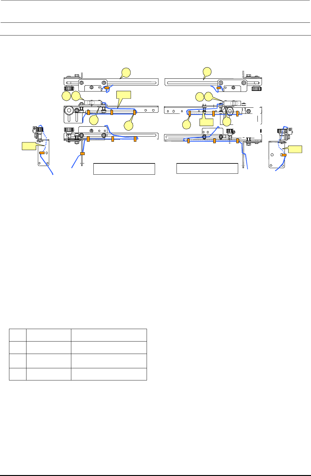
5-4. Replacing the IN and OUT Sensors
Bind the cables A and B with binding bands, taking care that they are not pulled or loosened
excessively during adjustment of sensor position.
Figure 5-4-1 IN and OUT Sensors
<Adjusting the sensitivity>
1) Make an adjustment so that a (matte) black glass epoxy PWB placed on the transport path can
be detected.
2) Place a (matte) black glass epoxy PWB under the sensor and rotate the sensitivity adjustment
knob of the sensor counterclockwise. Then gradually rotate it clockwise up to the position at
which the specified PWB is detected.
∗ If any black glass epoxy PWB is not available, use the PWB having the darkest color of those to
be used.
[List of Replacement Parts]
d
40002208
IN sensor assembly
e
40002210
OUT sensor assembly
f
SL4031291SC
SEMS cap bolt, M3×12
g
EA9500B0000
Tie-up band 60
Table 5-4-1 IN and OUT Sensors
d
c
f
g
e
A
B
Left-side sensor
d
e
c
g
f
B
A
Right-side sensor