JUKI FX-3R MAINTENANCE GUIDE.pdf - 第80页
FX-3R Maintenance Guide 7-1 DANGER To prevent any trouble caused by accidental machine start, always shut-down the power before starting the maintenance and adjustment work. [7] A TC After the ATC base has been replaced,…
FX-3R Maintenance Guide
6-1
DANGER
To prevent any trouble caused by accidental machine start, always
shut-down the power before starting the maintenance and
adjustment work.
[6] CAL BLOCK
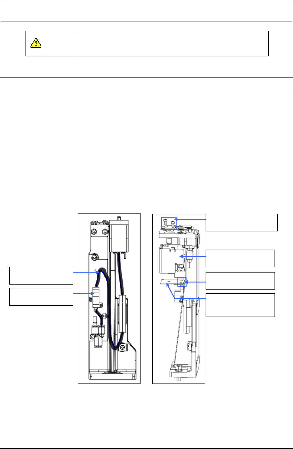
6-1. Replacing the CAL Board Assembly
(1) Disconnect the cables from the CAL board.
(2) Disconnect the φ4-air tube c from the air suction filter d.
(3) Remove the M3 cap bolts e (two locations) to detach the CAL side cover f.
∗ At this time, do not loosen any flat countersunk head screw, but remove only the M3-cap
bolt.
(4) Remove the M3 SEMS cap bolts g (two locations) to detach the board h from the CAL side
cover f and φ4-air tube c.
The CAL board assembly h can then be taken out.
(5) After the board has been replaced, reassemble the parts and components in the reverse order
of disassembly.
c BT0400251EB
φ4-air tube (black)
d PF0100030A0
Air suction filter
e SM6030602TN
SEMS cap bolt M3×6
f L202E521000
CAL side cover
g SL4030691SC
SEMS cap bolt M3×6
h 40007376
CALBLOCK board
assembly
Figure 6-1-1 Side View Figure 6-1-2 Front View
It is possible to replace the filter element inside the air suction filter d without shutting down of the
air supply.
Part No. PF901009000, Part name FILTER ELEMENT
Rev. 1.00
FX-3R Maintenance Guide
7-1
DANGER
To prevent any trouble caused by accidental machine start, always
shut-down the power before starting the maintenance and
adjustment work.
[7] ATC
After the ATC base has been replaced, it is necessary to obtain “ATC Offset” of the MS parameters
again. (See also section 3-9, in MS parameters.)
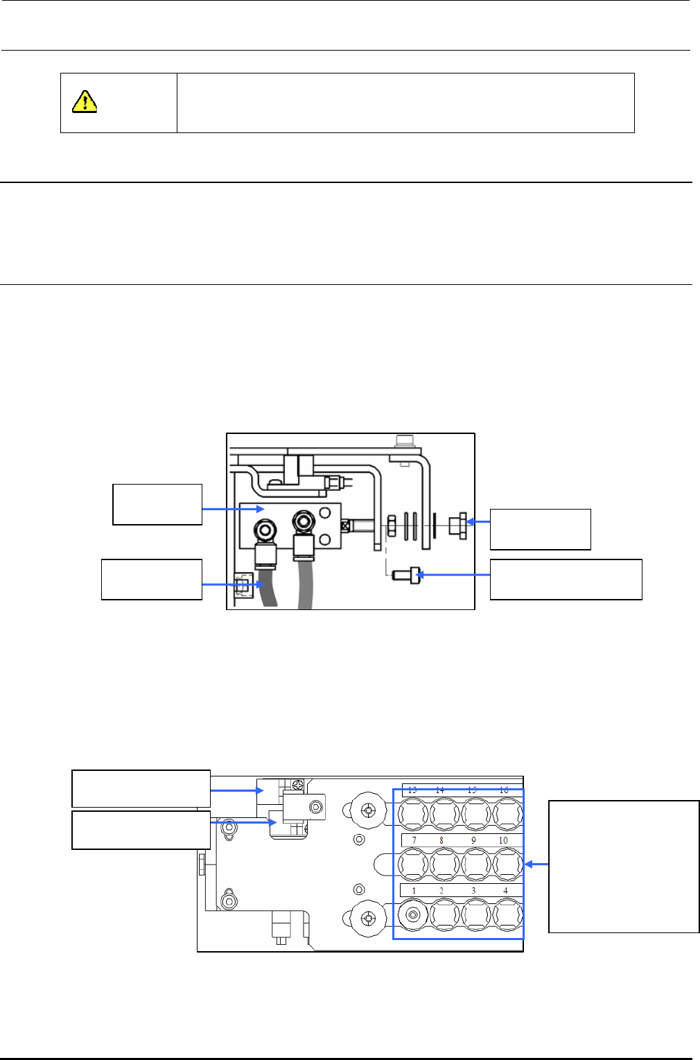
7-1. Replacing the Air Cylinder
1) Close the hand valve at the lower left portion of the main unit.
2) Remove the ATC joint and Hexagon socket head cap screw to detach the air cylinder. (At this
time, disconnect the φ4 air tube.)
3) Mount the speed controller on a new air cylinder.
BT0400251EA
Air tube φ4
40042709
Air cylinder
SM6040802TN
SEMS cap bolt M4×8
E3528729000
ATC joint
Figure 7-1-1 Replacing the Air Cylinder
4) Adjust the air cylinder rod fixing position.
With the slide plate open, visually adjust the position so that the hole on the ATC base matches
the center of the arc of the slide plate, then fit the nut supplied with the ATC cylinder to the ATC
joint.
At this time, apply Loctite 242 to the screw threads of the ATC joint.
ATC open sensor
assembly
ATC close sensor
assembly
Make the adjustment
so that the arc of the
slide plate is matched
with the center of the
hole in the base when
the slide plate is
opened.
Figure 7-1-2 Adjustment Position when Fixed
Rev. 1.00
FX-3R Maintenance Guide
7-2
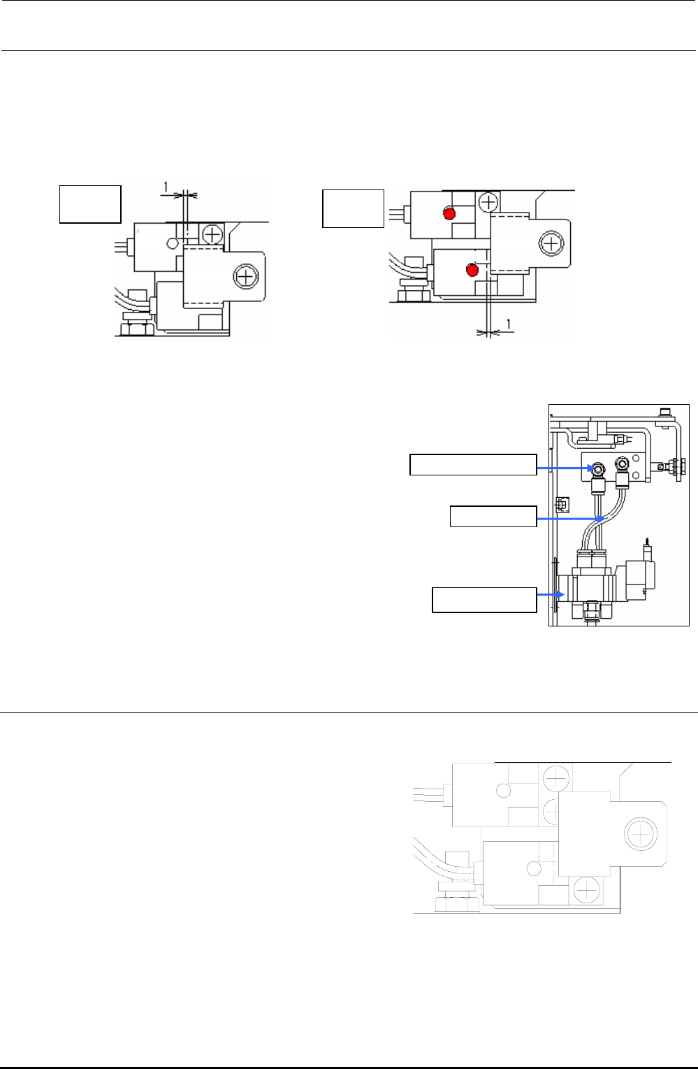
5) Adjust the sensor dog position
When opened: Open the slide plate and secure the dog at a position where the dog is further
moved 1mm after the LED goes off.
When closed: Close the plate. The plate must be stopped at a position where it is further
moved 1mm after the LED is lit.
Sensor
LED unlit
OPEN
sensor
Sensor
dog
Sensor
LED lit
CLOSE
sensor
Sensor
dog
Figure 7-1-3 When Opened
Figure 7-1-4 When Closed
6) Connect a φ4 air tube.
Refer to the Figure 7-1-5, and connect the speed controller to the
solenoid valve with an air tube (φ4).
Solenoid valve
Speed controller
Air tube
φ
4
Figure 7-1-5 Air Piping and Speed
Controller Positions
7-2. Replacing the ATC OPEN and CLOSE Sensors
1) Detach the sensor dog, and cut and
remove the tie-up bands from the fixing
base on the side of the ATC base.
OPEN
sensor
CLOSE
sensor
Sensor
dog
2) Replace the ATC OPEN or CLOSE
sensor assembly.
3) Secure the cables to the fixing base
with the tie-up bands and assemble the
sensor dog.
Figure 7-1-6 OPEN and CLOSE Sensors
Rev. 1.00