JUKI FX-3R MAINTENANCE GUIDE.pdf - 第82页
FX-3R Maintenance Guide 7-3 Rev. 1.00 7-3. Adjusting the Speed Controller 1) Rotate the knob of the speed controller to adjust the opening/closing time of the slide plate to the standard adjustment value. (As a guide, ro…
FX-3R Maintenance Guide
7-2
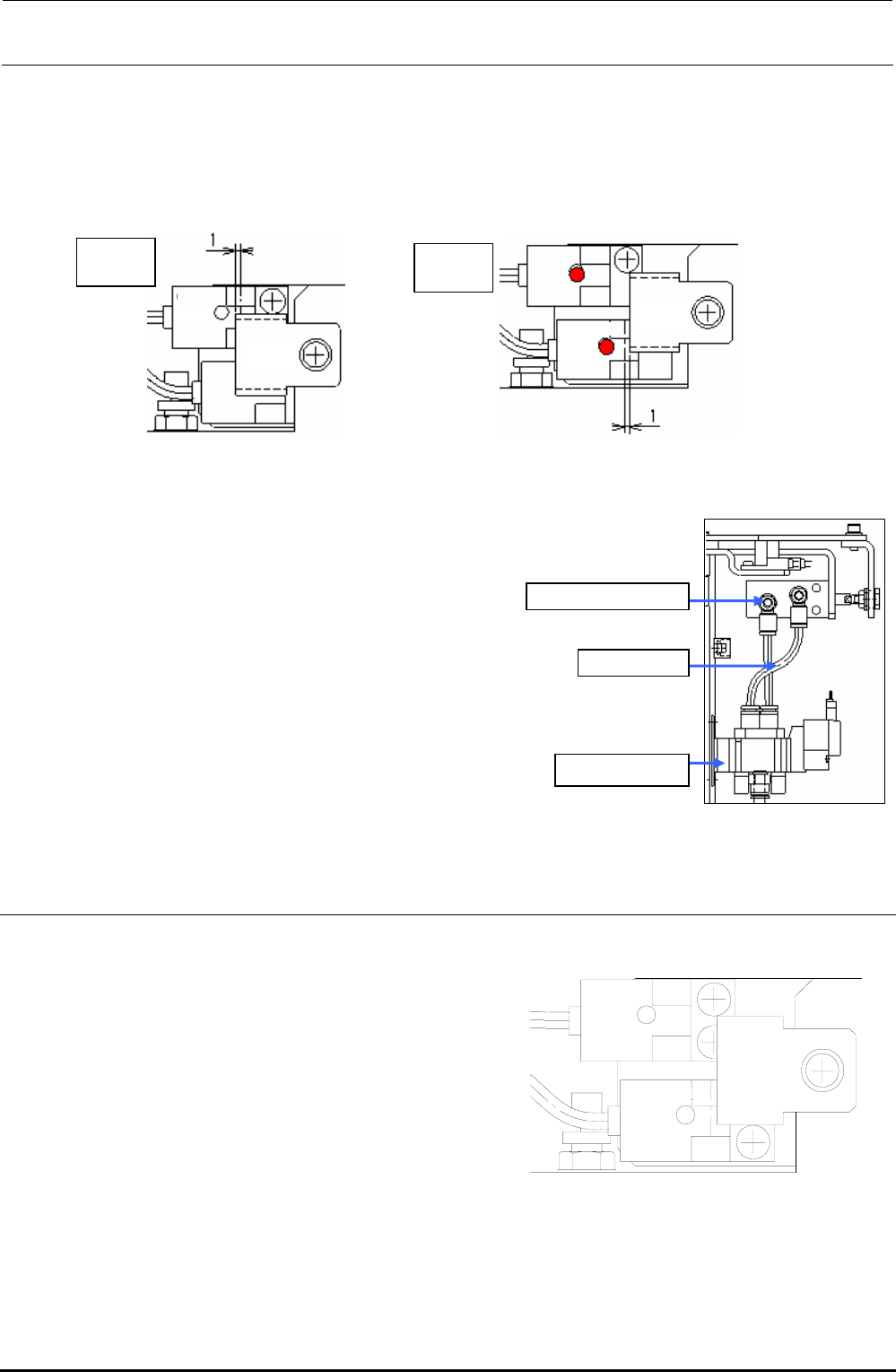
5) Adjust the sensor dog position
When opened: Open the slide plate and secure the dog at a position where the dog is further
moved 1mm after the LED goes off.
When closed: Close the plate. The plate must be stopped at a position where it is further
moved 1mm after the LED is lit.
Sensor
LED unlit
OPEN
sensor
Sensor
dog
Sensor
LED lit
CLOSE
sensor
Sensor
dog
Figure 7-1-3 When Opened
Figure 7-1-4 When Closed
6) Connect a φ4 air tube.
Refer to the Figure 7-1-5, and connect the speed controller to the
solenoid valve with an air tube (φ4).
Solenoid valve
Speed controller
Air tube
φ
4
Figure 7-1-5 Air Piping and Speed
Controller Positions
7-2. Replacing the ATC OPEN and CLOSE Sensors
1) Detach the sensor dog, and cut and
remove the tie-up bands from the fixing
base on the side of the ATC base.
OPEN
sensor
CLOSE
sensor
Sensor
dog
2) Replace the ATC OPEN or CLOSE
sensor assembly.
3) Secure the cables to the fixing base
with the tie-up bands and assemble the
sensor dog.
Figure 7-1-6 OPEN and CLOSE Sensors
Rev. 1.00

FX-3R Maintenance Guide
7-3
Rev. 1.00
7-3. Adjusting the Speed Controller
1) Rotate the knob of the speed controller to adjust the opening/closing time of the slide plate to
the standard adjustment value.
(As a guide, rotate the knob about two and a half turns from the fully closed position.)
2) After adjustment, fix the knob.
Check the slide plate opening/closing time on the Manual Control screen.
Standard value: Slide plate opening/closing time 80 ± 5 msec.
FX-3R Maintenance Guide
DANGER
To prevent any trouble caused by accidental machine start, always
shut-down the power before starting the maintenance and
adjustment work.
[8] FEEDER BANK, REPLACEMENT TABLE AND ELECTRIC BANK
(OPTIONAL)
8-1. Common Parts and Units for Mechanical Feeder and Electric Feeder
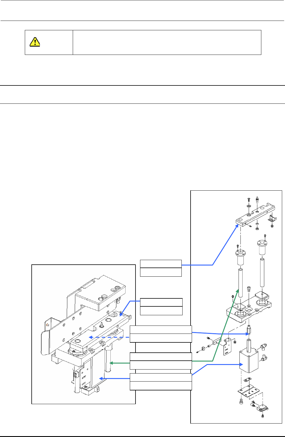
8-1-1. Replacing the Bank-Up Cylinder
1) Turn off the power to the main unit.
2) Turn on the selector switch, and the left and right roller levers to raise the bank lifter.
3) Loosen the lifter cylinder shaft to detach the bank-up cylinder (cylinder to be replaced).
4) Shut-down the main compressed air to the main unit (with the hand valve).
5) Remove the lifter supporter assembly mounting screws.
6) Pull out the bank lifter upward. (Bank lifter to be replaced)
7) Remove four bank-up cylinder mounting screws to detach the cylinder.
8) Mount the speed controller on a new cylinder.
9) Mount the cylinder and insert the bank lifter from the top.
10) Screw the lifter cylinder shaft into the cylinder rod.
11) Mount the lifter supporter.
12) Supply the main compressed air to the main unit.
13) Adjust the speed controllers of the left and right cylinders.
(Section 8-6.)
14) Mount the replacement table on the main unit.
15) Turn on the power.
8-1
Rev. 1.00
40047264
Bank lifter RS
40047265
Bank lifter LS
40047263
Lifter cylinder shaft 85
40047261
Lifter guide shaft 25
PA630850100
Air cylinder
Figure 8-1-1-1 Back-Up Cylinder Related Parts
Figure 8-1-1-2 Lifter Supporter