JUKI FX-3R MAINTENANCE GUIDE.pdf - 第71页
FX-3R Maintenance Guide 5-18 Rev. 1.00 5-13. Replacing the Backup Stopper (for EN T y pe Only) 1) Loosen the BU stopper bracket set screw h with the air turned ON to adjust the crosswise position of the BU stopper. Loose…
FX-3R Maintenance Guide
5-17
Rev. 1.00
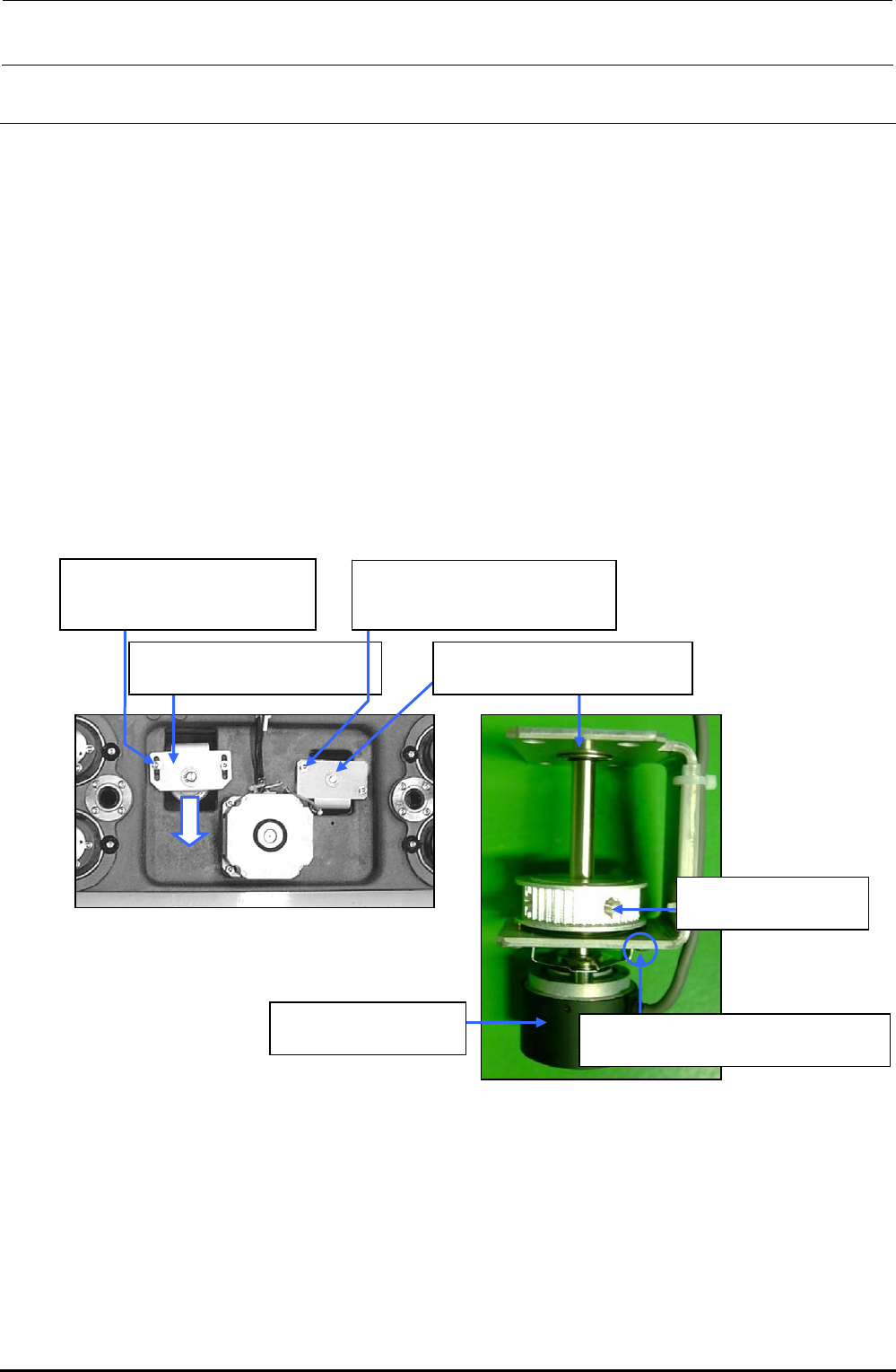
5-12. Replacing the Support Table ENC
1) Detach the support table in the same manner as described in 5-11, Replacing the support table
Motor.
2) Loosen the screw d, and move the tension support assembly c in the arrow direction to
loosen the tension of the timing belt
3) Loosen the screw f to detach the encoder bracket assembly e.
4) Loosen the screw supplied with the encoder (hollow set screw h) and fixing screw i to detach
the BU ENC assembly g.
5) When installing a new BU ENC, reassemble the components in the order of steps 4) to 1).
Adjust the flatness of the support table as described in 5-11 “Replacing the Support Table
Motor.”
After the components have been reassembled, obtain the support table offset from MS
parameters.
d SL6051492TN
SEMS cap bolt with washer
M5×14
c 40000937
Tension support assembly
f SL6051492TN
SEMS cap bolt with washer
M5×14
g E94337290A0
BU ENC Assembly
h SM8040802TP
Set screw M4×8
e 40000934
Encoder bracket assembly
i SL6030692TN
SEMS cap bolt with washer M3×6
Figure 5-12-2 BU ENC Assembly
Figure 5-12-1 Conveyor Base Assembly (L)
FX-3R Maintenance Guide
5-18
Rev. 1.00
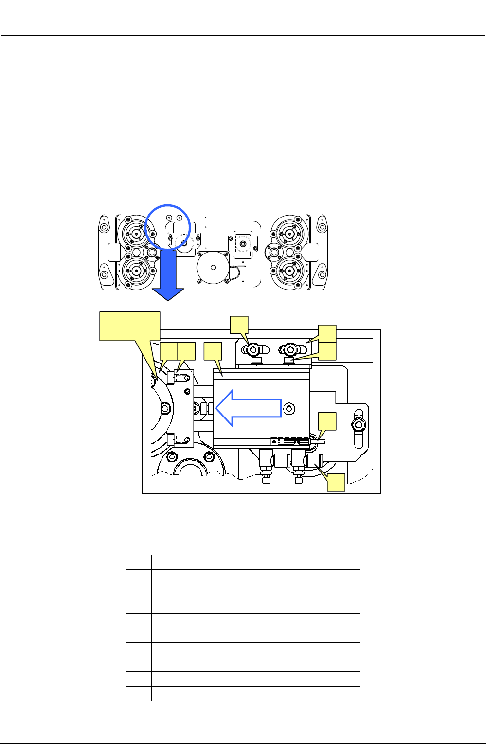
5-13. Replacing the Backup Stopper (for EN Type Only)
1) Loosen the BU stopper bracket set screw h with the air turned ON to adjust the crosswise
position of the BU stopper. Loosen the air cylinder set screw f and make the adjustment so
that the height of the BU stopper (rubber part) c is matched with the height of the flange outer
periphery of the ball screw. After that, check that the dimension A shown in the right portion of
Figure 5-8-1 is 5 mm.
2) For the lock sensor position of the BU stopper, loosen the BU lock sensor set screw k, move
the sensor from the cylinder retract status in the B direction. After the sensor has been turned
ON (LED goes off), further move the sensor 1 mm and secure it firmly.
3) To adjust the speed controller, loosen the lock nut of the speed controller j, turn the speed
controller 3 rotations from its fully closed position, and then secure it with the lock nut.
Figure 5-13-1 Backup Stopper
[List of Replacement Parts]
Table 5-13-1 Replacement Parts of Backup Stopper (Reference for PWB Positioning Hole)
Part No. Part name
c
40000970 BU_STOPER
d
SM6051002TN SCREW
e
PA150101100 DUAL_AIR_CYRINDER
f
SL6040892TN SCREW
g
40000971 BU_STOPER_BRACKET
h
SL6051492TN SCREW
i
BT0400251EA AIR_TABE
j
PC010508000 SPEED_CONTROLLER
k
40002241 BU_LOCK_CABLE_ASM
cd e f
g
h
j
k
Ball screw
flange
“B” direction
FX-3R Maintenance Guide
5-19
Rev. 1.00
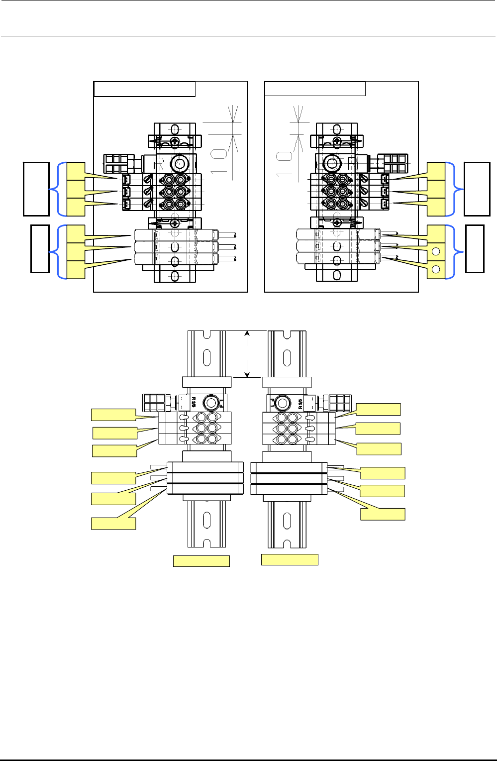
For details about how to replace the parts and connect the cables and piping inside the solenoid
valve assembly, see Figure 5-13-2.
Figure 5-13-2 Solenoid Valve Assembly L Specification
43mm
C-OUT
STOP
WAIT
STOPPER
SHAPE Y
BU(EN)
BU(EN)
SHAPE Y
STOPPER
C-OUT
WAIT
STOP
搬送ユニット L用
搬送ユニット R用
Figure 5-13-3 Solenoid Valve Assembly XL Specification
Amplifier
Solenoid
v
a
lv
e
d
[For transport unit L] [For transport unit R]
c
e
f
g
h
j
i
k
l
11
12
Amplifier
Solenoid
v
a
lv
e
For transport unit L
For transport unit XL