JUKI FX-3R MAINTENANCE GUIDE.pdf - 第30页
FX-3R Maintenance Guide 2-12 2-5. Replacing the Belts 2-5-1. Replacing the Timing Belt Z After the timing belt Z has been replaced, it is absolutely necessary to re-input the MS parameters related to the Z-axis home posi…
FX-3R Maintenance Guide
2-11
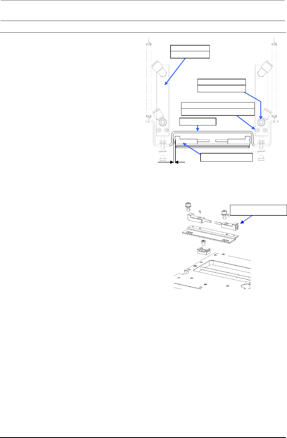
2-4. Replacing the Head Up Cylinder
Rev. 1.00
1) Turn the finger valve to stop the air supply
and disconnect the air tubes.
2) Remove the head up springs from both
ends, and then remove the nut from the
top end of the air cylinder to detach the
release bar. (Pay special attention so that
the wave washer is not lost.)
3) Remove the cap bolts c (×2) securing the
air cylinder to detach the air cylinder.
(When replacing only the nozzle down
sensor, it is not necessary to detach the
air cylinder.)
4) Remove the cap bolts (×2) securing the
nozzle down sensor bracket to detach the
nozzle down sensor together with the
bracket.
(If the nozzle down sensor needs to be
replaced:)
5) When mounting the air cylinder, adjust the
end face so that it is in parallel to the
cylinder mount and secure them.
Figure 2-4-1 Head-up Cylinder Adjustment
Position
2mm
Nozzle down sensor
c SM6033002TN
SEMS cap bolt M3×30
40046524
Air cylinder
Release bar
PC0105080000
Speed controller
Nozzle down sensor
Figure 2-4-2 Mounting of Nozzle
Down Sensor
6) Mount the nozzle down sensor.
Adjust the nozzle down sensor bracket
position so that the clearance between
the sensor and release bar is 2 mm.
7) If the speed controller has also been
replaced, it is necessary to carry out the
adjustment before mounting the release
bar.
<Speed controller adjustment procedure>
c Call up the MS parameters from the top menu and select [Simple Control] → [MSP] tab in
the function bar. In this status, press the emergency stop button.
d Select [nozzle up cylinder] and turn ON or OFF the cylinder to adjust the displayed time
(msec.) to the specification value. Adjust the time by turning the knob of the speed controller.
Specification value: Air cylinder down time…140±5 msec.
(The difference between the left and right is 5 msec. or less.)
e After the adjustment has been completed, secure the knob firmly.
(8) Insert the release bar into the rod of the cylinder, put the wave washer, and turn the release bar
until the cylinder nut is stopped.
(At this time, it is not necessary to adjust the speed controller and MS parameter.)
∗ Manually operate the solenoid valve to check that the release bar moves up or down
smoothly.
FX-3R Maintenance Guide
2-12
2-5. Replacing the Belts
2-5-1. Replacing the Timing Belt Z
After the timing belt Z has been replaced, it is absolutely necessary to re-input the MS parameters
related to the Z-axis home position adjustment, Z-axis height, and laser. (For details of input items,
see section 2-7.)
Rev. 1.00
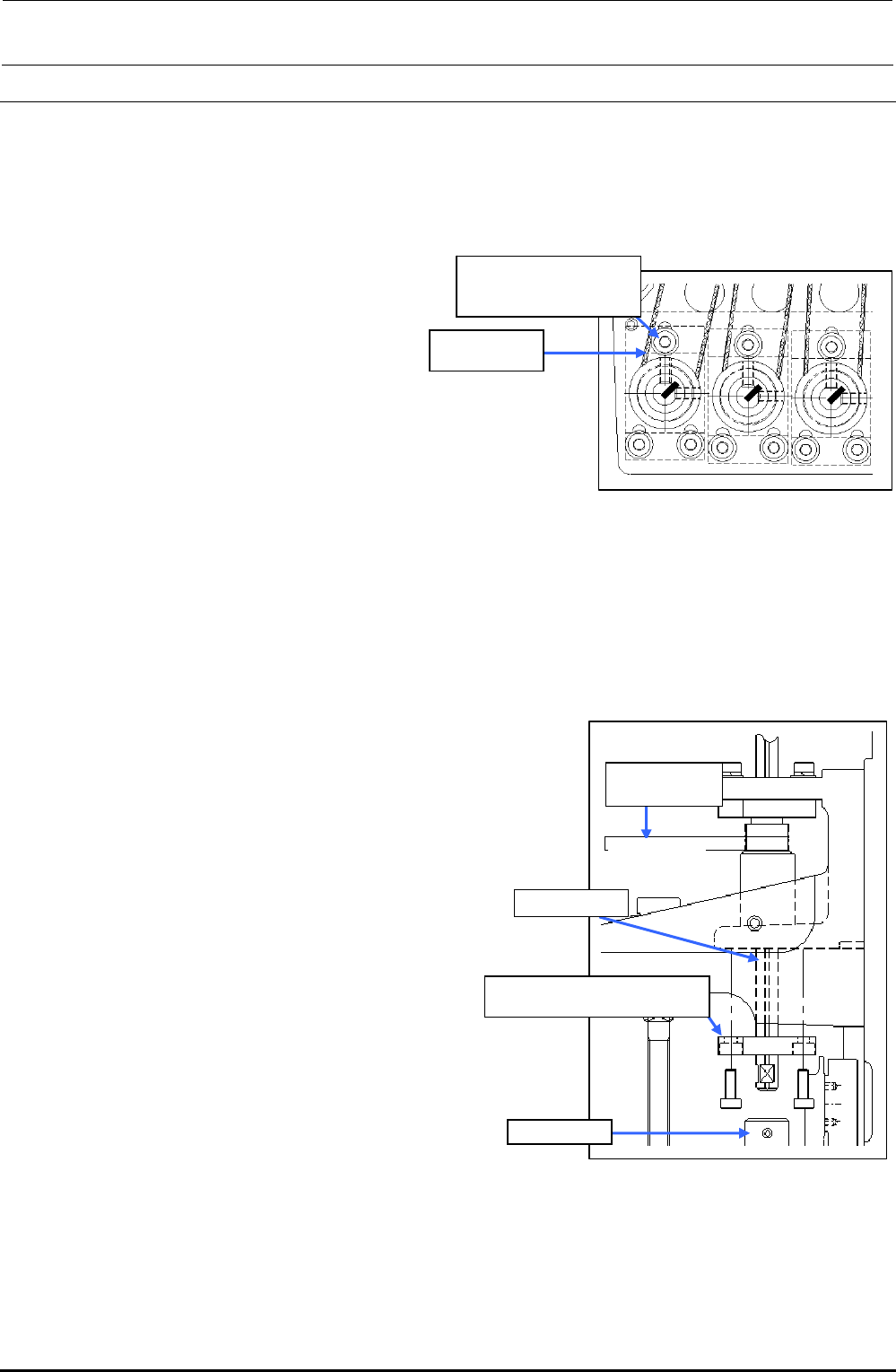
1) Loosen the SEMS cap bolts c (×3) shown
in the figure on the right.
2) Replace the timing belt Z.
3) Reassemble the components in the
reverse order of disassembly.
∗ Apply Loctite 242 to the Z-motor
mounting screws (3 pcs.) and tighten
them with a tightening torque of 2.3 N・m.
c SL6031692TN
SEMS cap bolt with
washer M3×16
40046522
Timing belt Z
Figure 2-5-1 Removing the Z-motor
∗ Adjust the belt tension following section 2-2-1.
2-5-2. Replacing the Timing Belt θ
After the timing belt θ has been replaced, it is absolutely necessary to re-input the MS parameters
related to the Z-axis home. (For details of input items, see section 2-7.)
1) Detach the bearing base c.
(L1 to L3: bearing base LL, L4 to L6: bearing base LR)
2) Detach the ball spline from the coupling d.
3) Pull out the spline housing downward and the spline
shaft upward.
4) Replace the timing belt θ.
5) Reassemble the components in the reverse
order of disassembly.
∗ When the bearing base L is secured, make sure that
the shaft is rotated smoothly.
∗ Adjust the belt tension following section 2-2-2.
L1 to L3: Bearing base LL c
L4 to L6: Bearing base LR c
Ball spline
Coupling d
40046521
Timing Belt T
Timing Belt θ
Figure 2-5-2 Replacing the
Timing Belt θ
FX-3R Maintenance Guide
2-13
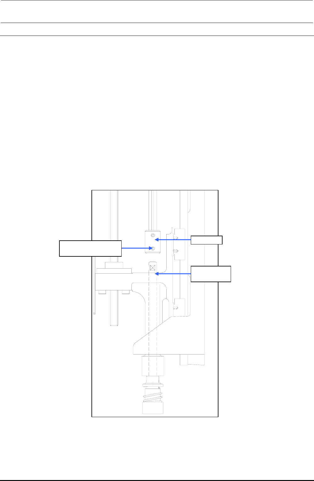
2-6. Replacing the Z-Slide Shaft
When the Z-slide shaft has been replaced, it is necessary to input the MS parameters related to the
θ-axis and Z-axis home position adjustment, Z-axis height, and laser again.
(For details about input items, see section 2-7.)
(1) Remove the hollow set screw c (×1) from the lower portion of the coupling.
(2) Detach the Z-slide shaft from the Z-slide bracket.
(3) Reassemble the components in the reverse order of disassembly.
∗ Secure the coupling with it kept pushed-in and make sure that any vertical play does not
exist on the slide shaft.
∗ When tightening the set screws of the coupling, align the flat part of the slide shaft with
the orientation of the coupling set screw. Tighten the set screw with a tightening torque of
0.5 N・m.
Rev. 1.00
c SM8030312TP
Set screw M3 L=3
Coupling
40044586
Z-slide Shaft
Figure 2-6-1 Z-slide Shaft