JUKI FX-3R MAINTENANCE GUIDE.pdf - 第90页
FX-3R Maintenance Guide 8-8 8-2. Bank and Replacement Table for Mechanical Feeder 8-2-1. Overall Drawing 40063859 Drive cylinder 40047264 Bank lifter RS 40047249 Drive brac ket E2708729000 Driver bracket (30) 40047265 Ba…
FX-3R Maintenance Guide
8-7
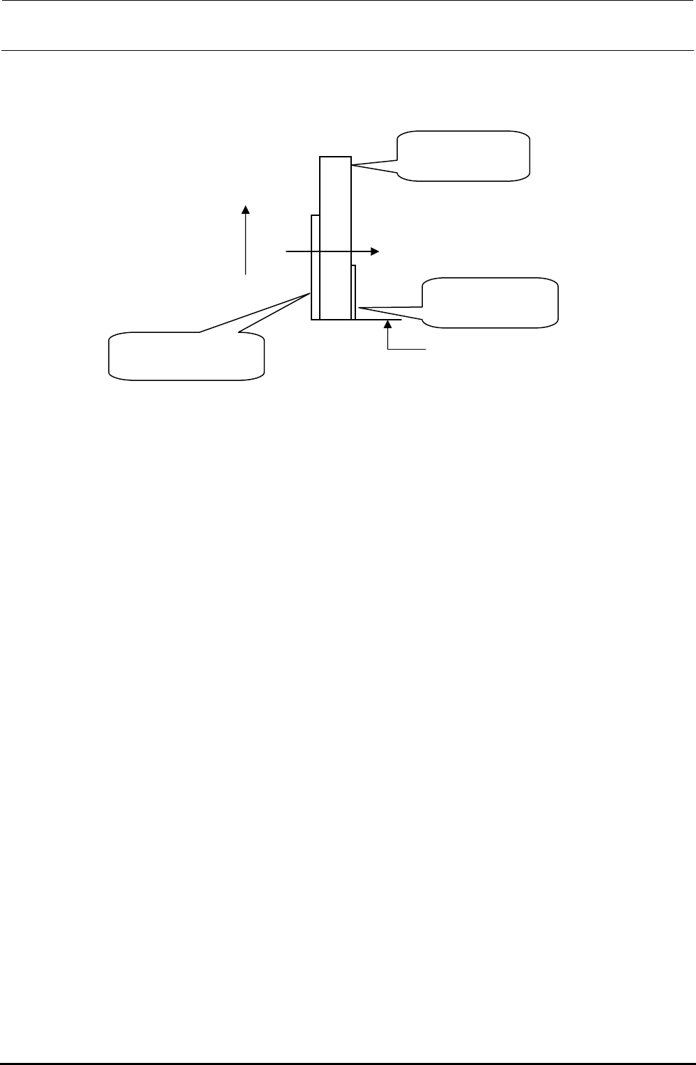
3) When mounting the antenna array, mount it so that the positional relationship is as follows.
Note that it is not allowed to reuse the conductive tape (HX002680000).
UP
Tightening direction
Make the tape matched
with the lower end position.
Shield bracket 60
40081207
Antenna array
40073664
Conductive tape
HX002680000
Figure 8-1-7-3 Cautions on Antenna Array Assembly
4) After the replacement has been completed, connect the antenna to the mounter or Intelli trolley
pool and make sure that the CH∗ LED on the MPC connected flashes.
Rev. 1.00
FX-3R Maintenance Guide
8-8
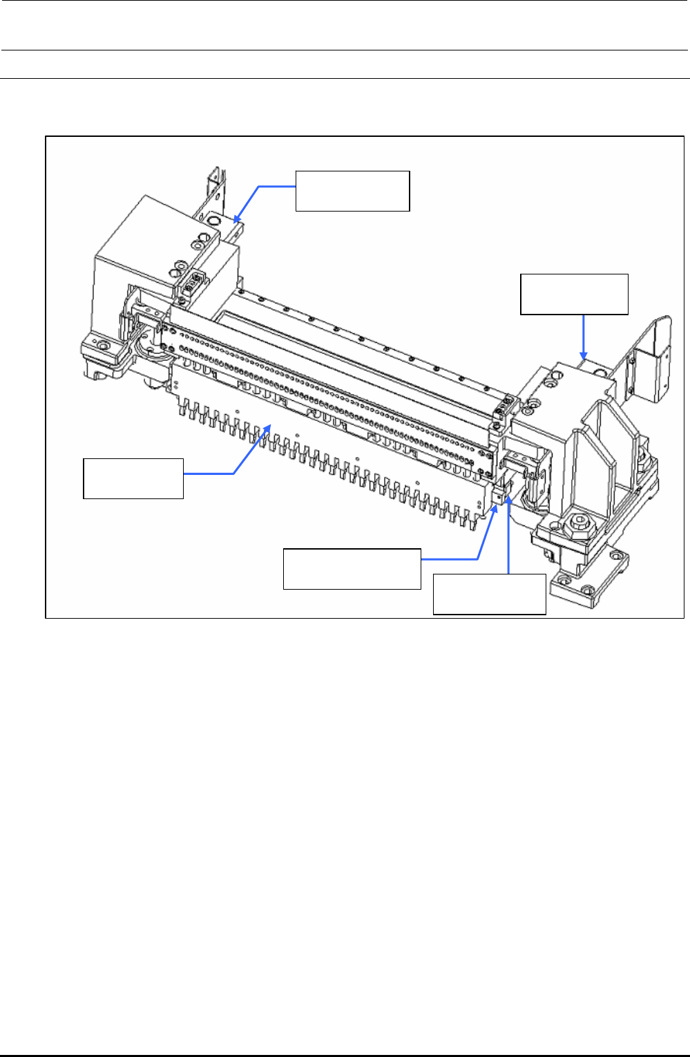
8-2. Bank and Replacement Table for Mechanical Feeder
8-2-1. Overall Drawing
40063859
Drive cylinder
40047264
Bank lifter RS
40047249
Drive bracket
E2708729000
Driver bracket (30)
40047265
Bank lifter LS
Figure 8-2-1-1 Overall Drawing
Rev. 1.00
FX-3R Maintenance Guide
8-9
8-2.2. Replacing the Drive Cylinder
1) Turn OFF the power to the main unit completely before starting the replacement work.
2) Shut-down the main pressure air to the main unit (with the hand valve). If the machine is
equipped with an optional replacement table, disconnect the air tube and move the
replacement table outside the main unit.
3) Disconnect the left and right air tubes and connectors.
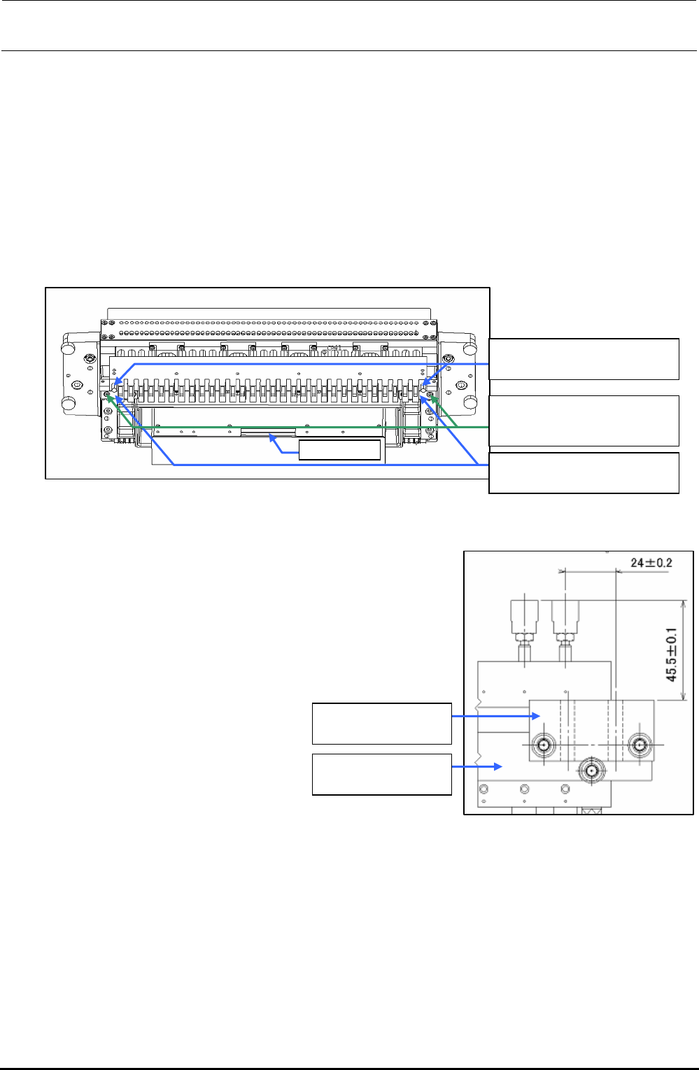
4) Remove the driver bracket mounting screws.
BT0600400EC
Air tube φ6
40047249
Drive bracket
SL6053092TN
SEMS cap bolt with washer
M5×30
Connector
Figure 8-2-2-1 Part Names (When Viewed Slantwise from the Lower Portion)
5) Replace the drive cylinder with a new one and mount the
driver bracket (30) and drive bracket.
For details about assembly and adjustment work, see the
Figure on the right.
6) Reassemble the components in the reverse order of
disassembly.
40047249
Drive bracket
E2708729000
Driver bracket (30)
Figure 8-2-2-2 Drive Bracket Assembly Positions
Rev. 1.00