SS-1189-002.pdf - 第12页
10 SS-1189 18. Environmental Requirements for Bank Feeder Cange Cart Floor Gradient : 10/ 1000 or less Note : The casters of the cart shall be rigid enough to move smoothly. 0707-002
9
SS-1189
11. Number of
Installable Feeders
(1) Tape Feeders
Max. 100 feeders (25 feeders × 4 feeder bases)
(When only 8 mm dual tape feeders are used)
Ref. : Up to 200 types of components can be used.
Max. 100 feeders (when only 12/16 mm tape feeders are used)
Max. 48 feeders (when only 24/32 mm tape feeders are used)
Max. 32 feeders (When only 44/56 mm tape feeders are used)
Max. 24 feeders (When only 72 mm tape feeders are used)
(2) Vibratory Stick Feeders
Max. 4 per feeder base
Ref. : Up to 6 carrier sticks can be installed on one vibratory stick feeder.
Notes : (a) The number of installable feeders varies according to the
combination of the reel width for the taping and the feeders.
(b) Use the tape feeders used prepared specially for GXH series.
The tape, dual tape and bulk feeders for the other machines cannot
be used.
Supply Pressure 0.45 to 0.69 MPa (4.6 to 7 kgf/cm ²)
Set Pressure 0.45 MPa (4.6 kgf/ cm²)
Note : Min. 0.4 MPa (4.1 kgf/ cm²) of air pressure is
necessary for operation.
12. Air Supply
Note : Use the dry and clean air as follows
Moisture : Dew Point −17°C or lower (Atmospheric Pressure)
Oil : 0.1 mg/m
3
or less (ANR)
Dust : Solid Material 0.01 μm or less
13. Air Consumption Approx. 160 L/min (normal condition)
Note : Approximately 40 L/min (normal condition) is consumed while one
feeder base is moving up.
14. Vacuum Pressure
−93 kPa (70 cmHg)
15. Environmental
Condition
Temperature : 20
±
10
°
C
Humidity : 30 to 80 % (Avoid dew condensation)
Note : When the ambient temperature rises more than the surface of the
machine, dew may condense under the condition described below.
Note that dew condensation may cause the machine to break down.
Condition of Dew Condensation
Dew may condense when the differences (based on "Humidity (%)")
between the ambient and surface temperatures of the machine reach the
values or more in the table below.
16. Dimensions
Approx. 2,664 (width) × 2,350 (depth) × 1,400 (height) mm
Notes : (a) The width includes the Carrier / Rejected conveyor.
(b) The depth becomes 2,580 mm when the Bank Feeder Change Cart
is included.
(c) The height becomes 2,100 mm when the light tower is included.
17. Mass Approx.
3,000 kg (excl. the Bank Feeder Change Carts and the tape feeders)
0707-002
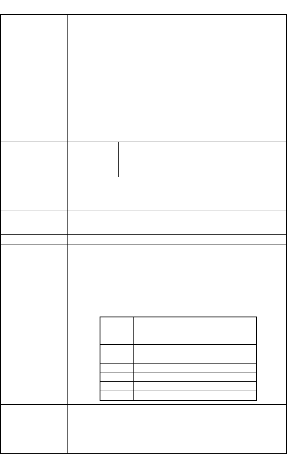
Humidity
(%)
Differences between Ambient and Surface
Temperatures of Machine (Ambient
Temperature > Surface Temperature)
80 3 °C or more
70 6 °C or more
60 8 °C or more
50 10 °C or more
40 14 °C or more
30 18 °C or more

10
SS-1189
18. Environmental
Requirements for
Bank Feeder
Cange Cart
Floor Gradient : 10/1000 or less
Note : The casters of the cart shall be rigid enough to move smoothly.
0707-002
11
SS-1189
3.2 Electrical Specifications
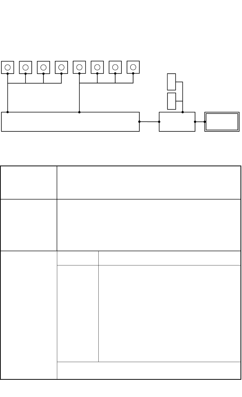
3.2.1 Control Configuration
Comera for Component
Recognition
Camera for P.E.C.
Recognition
Recognition Processor
Main Machine
Controller
Main Machine
of GXH
Monitor can be used both as operation
and recognition
(fitted with a touch screen)
Front Side
Rear Side
L
C
D
L
C
D
1
2
3
4
1
2
3
4
Fig. 7
3.2.2 Electrical Specifications
1. Memory Capacity
of Pattern Program
Data
Max. Number of Steps : 20,000 steps/ model
Max. Memorized Number of Models : 500 models
Note : The above numbers may be limited according to the capacity of the
pattern program data per model.
2. Edit, Input System
and Output System
of Pattern Program
Data
• Pattern program data editing is possible, using the touch screen, the keyboard,
and the pointing device of the main machine.
• Pattern program data can be edited with the network terminal (Option).
• Data can be entered through the local area network (Ethernet) running from
the storage unit of the network terminal (Option).
• Data Reading Floppy Disk (Option)
• Data Transfer Storage of Network Terminal (Option)
Visual Field φ 62 mm
The dimension in Y direction must be 46.5 mm.
Photoimage Front Lighting System
(Direct Recognition of Component by Front Lighting)
Note : Some limitation is imposed, depending on the types
of components.
Back Lighting System
(Recognition by Component Silhouette)
Note : Some limitation is imposed, depending on the types
of components.
In the back lighting system, specified nozzle are
required for the middle-size odd-shaped components
and the multifunctional nozzle on the multifunctional
head.
3. Component
Recognition
Note : A proper camera is automatically selected according to the shape and
size of components.
0707-002