SS-1189-002.pdf - 第7页
5 SS-1189 • Pick-Up and Placement Up/Down-Axis (L-Axis) Control Function • Pick-Up Position (X/Y) Correction Control Function • Pocket outline recognition • Two-stage placement Z-Axis speed reduction • Nozzle existence c…
4
SS-1189
High Flexibility Function
• The optional multi-functional heads for head modules will make it possible
to mount larger varieties of components.
Technology of High Precision Component Placement
• Both X and Y axes are provided with linear motors and scales to realize the
high-speed・highly accurate component positioning.
Adoption of Linear Motors for X/Y Beam Driving
Fig. 5
• Servomotors are used to drive the head, making it possible to control the
head position with the encoder.
• A highly accurate mounting is always maintained by the automatic offset
teaching function, the self-calibration system, etc.
Comfortable Operation Environment
• A new operation environment is constructed and the self-diagnosis function
is enhanced, realizing the comfortable operation environment.
• When the machine was designed, the setup and maintenance work was
taken into consideration.
• The enhanced production support software realizes high productivity.
Other Functions
Standard Function
• Component Pick-Up Error Automatic Recovery Function
• Pick-up Location Teaching Function
• Pick-up Priority Function
• Alternate Function at Component Supply Section
• Programming Sorting Function
0707-002

5
SS-1189
• Pick-Up and Placement Up/Down-Axis (L-Axis) Control Function
• Pick-Up Position (X/Y) Correction Control Function
• Pocket outline recognition
• Two-stage placement Z-Axis speed reduction
• Nozzle existence check before pick-up
Options
• P.C.B height feed back function
• Soft mount nozzle
• Unit PCB B.B.R. Function
• Placement Coordinates Teaching Function
• Component Library Teaching Function
• Application for BGA/CSP
• Splicing
• Advance Notice and Instruction of Splicing
• Multiple Languages (Mandarin Chinese, Korean)
• Network Terminal
Programming Software
Pattern Program Optimization Software
Pattern Program Conversion Software (Our Products and Machines of
Other Brands)
CAD Conversion Software
Multi-Pattern Program Line Balance Software
Production Manager Software
• ACV System
Application Multi-tray (FP-G100,FP-G200)
P.C.B Traceability
• Off-line component library create system
• Application for large-sized board (Max. 610×460 mm)
• 2D bar code NC program change function
• High-resolution component recognition camera
• Flux dipping unit (Auto reload type / Manual reload type)
• Coplanarity check function
• Application for 0402
0707-002
6
SS-1189
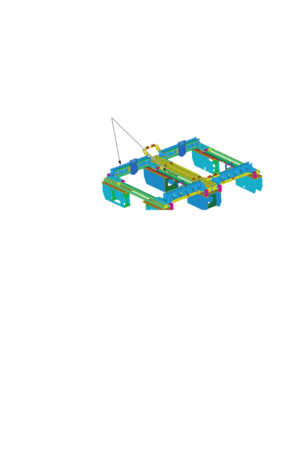
3. Specifications
3.1 Mechanical Specifications
3.1.1 Mechanical Construction
Fig. 6
3.1.2 Mechanical Specifications
1. Model Name GXH-3
2. Throughput 95,000 CPH
Note : The PCB transition time under optimum conditions is excluded.
3. PCB Transfer
Time
Approx. 2.5 seconds (PCB Length: 155 mm or less) (under optimum condition)
4. PCB Flow
Direction and
Transfer Reference
PCB Flow Direction : From Left to Right ("From Right to Left" is optional.)
Transfer Reference : Front Side of Machine or Rear Side of Machine
5. Applicable PCB
Size: 50 × 50 to 460 × 460 mm (Four Corners : R1 to R1.5 mm)
Thickness : 0.5 to 5.0 mm
Warpage : 0.2 mm or less per 50 mm Max. ± 1 mm
Mass : Max. 1.5 kg (completed PCB)
Material : Glass Epoxy
Ceramic (Option)
Note : Depending on the material, shape, warpage, mass, etc., of the PCB, it is
required to make a placement test to confirm that the components can be
placed normally.
0305-002 Tg0846-WO-SP
0707-002
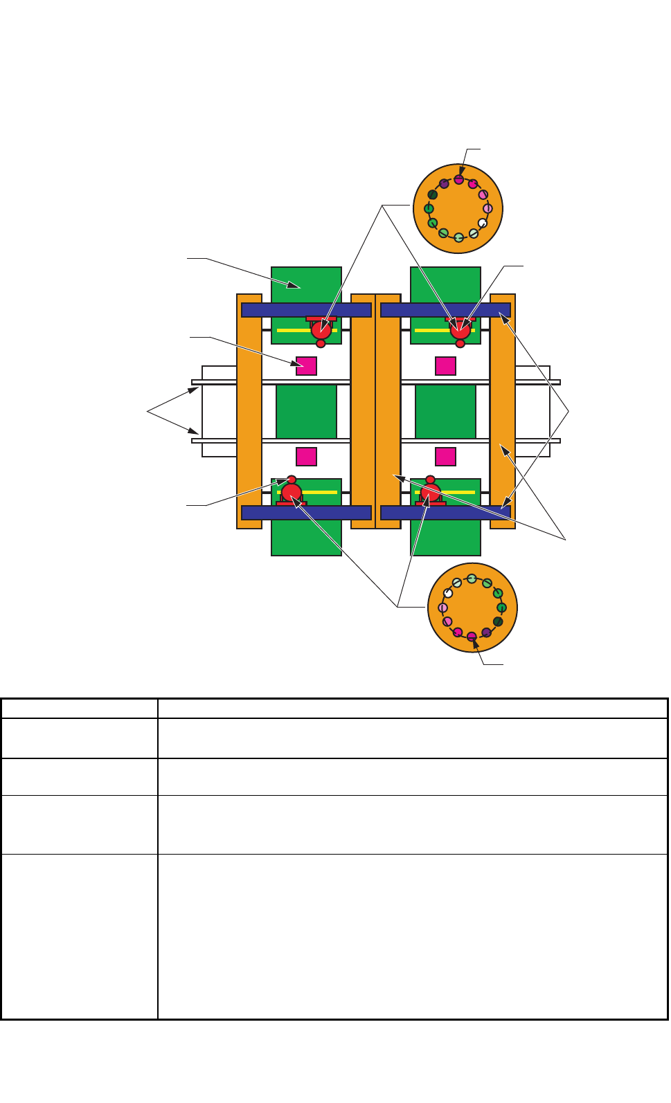
P.E.C Camera
PCB Transfer
Conveyor
Component
Recognition Camera
Feeder
X-axis
Y-axis
Head
Pick-Up Position
Pick-Up Position