SS-1189-002.pdf - 第4页
2 SS-1189 • The bank feeder change carts made it possible to reduce the feeder setup time. Fig. 2 • The tape splicing function is adopted to keep the machine running for continuous production. • The PCB Y position can be…

1
SS-1189
1. Scope
This machine is provided with a batch recognition system by which various
kinds of electronic components (simply called "Components" hereinafter) can
be recognized in batch and realizes highly accurate component placement on
the PCBs at high speed.
The machine is also equipped with four beams, four heads, and four
component recognition cameras, making it possible to handle many different
kinds of components in small lots or few different kinds of component in large
lots for diversified scales of production.
The machine introduces our latest technologies such as direct drive heads,
X/Y-axis linear motor driving, etc., that have been used in the past actual
production and is provided with various functions for reduction of OOS (out
of service) time. That is the reason why this high-speed mounter is called
"Direct Drive Modular Mounter with High Total Productivity for Next
Generation".
2. Features
Realization of High Productivity
• High productivity by the throughput of 95,000 CPH
• Each head has 12 nozzles and the shuttling frequency of the beams is
reduced, realizing high throughput.
• Linear motors are used to drive the X/Y axes, realizing the highly accurate
and reliable component placement at high speed.
• The nonstop batch recognition system realized the high-speed and highly
accurate recognition of components.
Collective Image Capture of 12 Components
(Example: 0603 to 4532)
Fig. 1
• Realization of "2.5 seconds or less" (PCB Transfer Speed with PCB Size
155 mm or less)
• The tape feeders are driven by the motors, realizing the high-speed and
reliable tape feeding performance.
0707-002
2
SS-1189
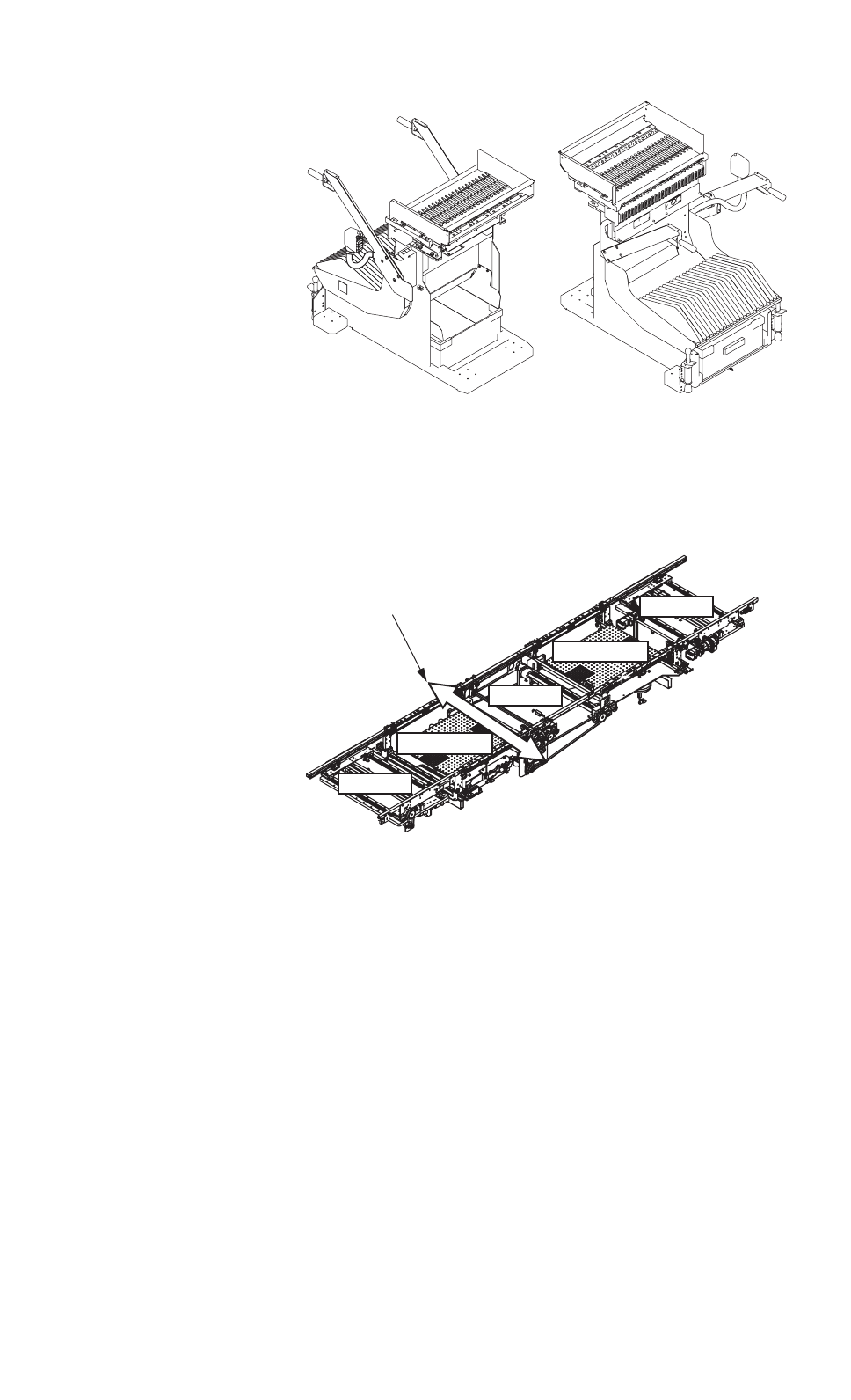
• The bank feeder change carts made it possible to reduce the feeder setup
time.
Fig. 2
• The tape splicing function is adopted to keep the machine running for
continuous production.
• The PCB Y position can be optimized to reduce the loss in cooperative
actions of the confronting beam.
PCB Flow Direction: From Left to Right
Fig. 3
• The PCB support pins can be exchanged collectively, improving the
internal setup performance.
• The internal optimization function made it possible to re-generate the
pattern program data according to the circumstantial changes for the
machine.
0402-003 Tg0911-WO-SP
0511-003 Tg0911-WO-SP 0707-002
Buffer
Input
Positioning
Positioning
Output
Optimization of PCB Y Position
Bank Feeder Change Cart
3
SS-1189
Realization of High Reliability
• Component thickness measurement
Linear measure sensor by the Component thickness measurement
• P.C.B upper surface measurement
Measure the P.C.B upper surface by the P.C.B height feed back function
• Soft placement
Soft mount nozzle to place the component lightly
• Each nozzle is provided with an electromagnetic valve to realize the
optimum control of vacuum ON/OFF actions.
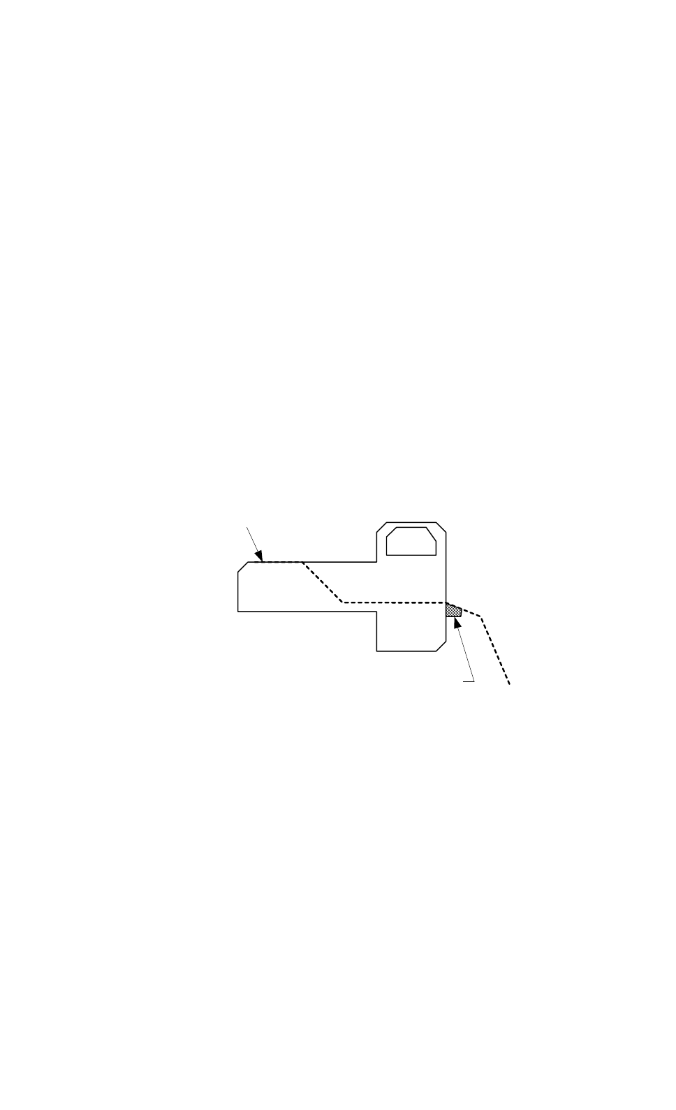
• The following effects can be expected by using the tape feeder provided
with a joint detection unit.
Preventing the mis-placement of spliced and replenished components
Eliminating pickup errors caused due to component shortage
Establishing traceability under component replenishment (tape splicing)
Correcting the count (the number of remaining components)
Operating Condition
Applicable Feeders : GD-18080, GD-18081, GD-18082
GD-12161, GD-24321, GD-44561
Operation Mode : "Enable" for "Component Remain Mode"
Component ID Lookup : Used together with the ACV system (option)
※ It is also possible to use the tape feeders for GXH-1 series
However the cycle time of component pick-up is longer than one for the
GXH-3 series tape feeders
Tape feeder provided
with a joint detection unit
Vacuum point
Fi
g
.4
0707-002