SS-1189-002.pdf - 第9页
7 SS-1189 6. Correction Method for PCB Location PEC Recognition 7. Conditions of PCB before Placement (Regulation of Component Height) Upper Level : Max. 12.7 m m Lower Level : Max. 30 mm 8. Applicable Components (1) App…
6
SS-1189
3. Specifications
3.1 Mechanical Specifications
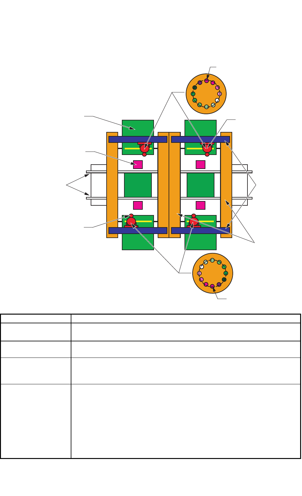
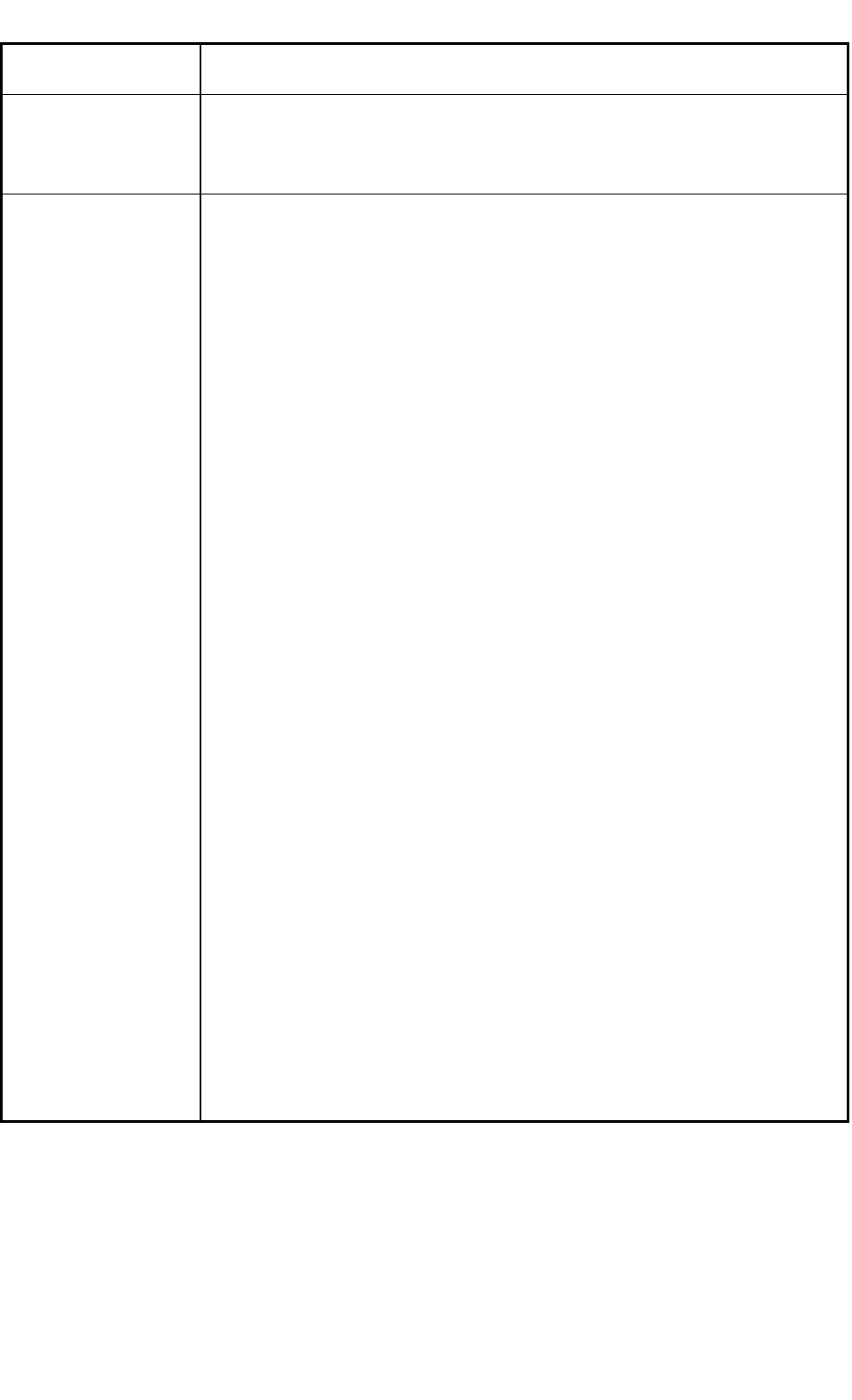
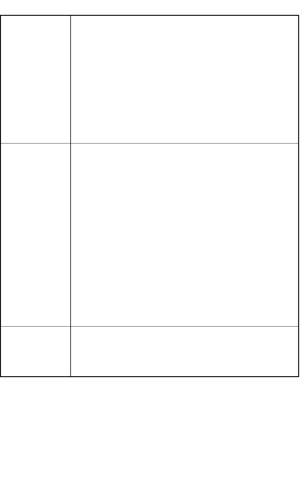
3.1.1 Mechanical Construction
Fig. 6
3.1.2 Mechanical Specifications
1. Model Name GXH-3
2. Throughput 95,000 CPH
Note : The PCB transition time under optimum conditions is excluded.
3. PCB Transfer
Time
Approx. 2.5 seconds (PCB Length: 155 mm or less) (under optimum condition)
4. PCB Flow
Direction and
Transfer Reference
PCB Flow Direction : From Left to Right ("From Right to Left" is optional.)
Transfer Reference : Front Side of Machine or Rear Side of Machine
5. Applicable PCB
Size: 50 × 50 to 460 × 460 mm (Four Corners : R1 to R1.5 mm)
Thickness : 0.5 to 5.0 mm
Warpage : 0.2 mm or less per 50 mm Max. ± 1 mm
Mass : Max. 1.5 kg (completed PCB)
Material : Glass Epoxy
Ceramic (Option)
Note : Depending on the material, shape, warpage, mass, etc., of the PCB, it is
required to make a placement test to confirm that the components can be
placed normally.
0305-002 Tg0846-WO-SP
0707-002
P.E.C Camera
PCB Transfer
Conveyor
Component
Recognition Camera
Feeder
X-axis
Y-axis
Head
Pick-Up Position
Pick-Up Position
7
SS-1189
6. Correction Method
for PCB Location
PEC Recognition
7. Conditions of PCB
before Placement
(Regulation of
Component Height)
Upper Level : Max. 12.7 mm
Lower Level : Max. 30 mm
8. Applicable
Components
(1) Applicable Components
Size : 0.6 × 0.3 to 44 × 44 mm or less
Thickness
: Max. 12.7 mm
Lead Pitch : 0.4 mm pitch or more
Lead Width : Min. 0.15 mm
Lead Length : Min. 0.20 mm
Note : Some components cannot be used due to the mechanical characteristics,
shapes, etc.
(Example of Unsuitable Components)
When there is a protruding portion on the upper surface of a component, the
lower surface of the vacuum nozzle may be worn out, causing an error during
the teaching operation through component recognition lighting.
Be sure to check the shape of the components to be used.
Applicable Components for Reference
• Cylindrical Components
Resistors, Capacitors, Diodes,
and other similar-shaped components,
• Square Components
Resistors, Film Capacitors, Coils,
Chip Ceramic Filters, and other similar-shaped components
• Deform Components
Semi-Fixed Variable Resistors, Trimmer Capacitors
and other similar-shaped components
• Ics
Mini-Flat ICs, Plastic Chip Carrier with Leads,
and other similar-shaped components
• Leaded Components
Mini-Mold Transistors, Mini-Power Transistors, Filters, LEDs, Diodes,
Coils, Tantalum Capacitors, Aluminum Electrolytic Capacitors,
and other similar-shaped components
• Connectors
Connectors for FFC / FPC, PCB-to-PCB Connectors,
Wire-to-PCB Connectors, PLCC Sockets,
and other similar-shaped components
• BGA/CSP Components (Option)
BGA, CSP, LGA, and other similar-shaped components
Size : Max. 44 × 44 mm
Ball Diameter : Min. φ 0.3 mm
Ball Pitch : 0.5 mm pitch or more
0707-002
8
SS-1189
(2) Packaged Posture Standards
Taped Components
JIS or its equivalent
• Paper Tapes (Width : 8 mm)
• Embossed Tapes (Width : 8 to 72 mm)
• Reel Outer Diameter : φ 382 mm or less.
Note : Some taping sizes are limited.
Some taped components cannot be used due to the mechanical
characteristics.
Stick Components
• Carrier Stick : Width 8 to 60 mm × Thickness 3 to 16 mm
× Length 400 to 600 mm (CS-G100 used)
Tray Components
• Tray : 100 × 100 to 323 × 136 mm (FP-G100 and FP-G300 used)
100 × 100 to 330 × 230 mm (FP-G200 used)
9. Placement Heads Equipped with 4 heads/4 beams
Vacuum Nozzle: Max. 12 nozzles on each head
Ref. : Maximum Number of Component Picks:
Component Size 5 × 4 mm or less 12
to 10 × 10 mm or less 6
to 12 × 12 mm or less 4
to 20 × 20 mm or less 2
to 44 × 44 mm or less 1
Note : There are two types of nozzles-one for high-speed component placement
and the other for middle-size odd-shaped component placement.
Although the nozzles for high-speed and middle-size odd-shaped
components can be used together, the nozzles for middle-size
odd-shaped components must be attached, leaving one out of every two
pitches empty due to the location of the diffusion plates.
Nozzle for High-Speed Component Placement :
The diameter is φ6 mm or less. This nozzle is used for 0603
components (Size : 0603 to 20
× 20 mm).
Nozzle for Middle-Size odd-shaped Component Placement :
The diameter is φ12 mm or less. The nozzle end is processed
according to the applicable components.
The nozzle can be used for the component size of up to 44 × 44
mm.
10. Number of
Stocked Nozzles
Max. 12 nozzles can be stored for each head.
Notes : (a) When some nozzle stockers are mounted additionally (optional
specifications), up to 48 nozzles can be stored for each head.
(b) When the vacuum nozzles for the middle-size odd-shaped
components are used, the nozzle stockers (a housing in which eight
nozzles can be stored) is required for the nozzles.
0305-002 Tg0846-WO-SP
0608-003 Tg1333-WO-SP 0707-002