SS-1189-002.pdf - 第8页
6 SS-1189 3. Specifications 3.1 Mechanical Specifications 3.1.1 Mechanical Construction Fig. 6 3.1.2 Mechanical Specifications 1. Model Name GXH-3 2. Throughput 95,000 CPH Note : The PCB transition tim e under optimum co…

5
SS-1189
• Pick-Up and Placement Up/Down-Axis (L-Axis) Control Function
• Pick-Up Position (X/Y) Correction Control Function
• Pocket outline recognition
• Two-stage placement Z-Axis speed reduction
• Nozzle existence check before pick-up
Options
• P.C.B height feed back function
• Soft mount nozzle
• Unit PCB B.B.R. Function
• Placement Coordinates Teaching Function
• Component Library Teaching Function
• Application for BGA/CSP
• Splicing
• Advance Notice and Instruction of Splicing
• Multiple Languages (Mandarin Chinese, Korean)
• Network Terminal
Programming Software
Pattern Program Optimization Software
Pattern Program Conversion Software (Our Products and Machines of
Other Brands)
CAD Conversion Software
Multi-Pattern Program Line Balance Software
Production Manager Software
• ACV System
Application Multi-tray (FP-G100,FP-G200)
P.C.B Traceability
• Off-line component library create system
• Application for large-sized board (Max. 610×460 mm)
• 2D bar code NC program change function
• High-resolution component recognition camera
• Flux dipping unit (Auto reload type / Manual reload type)
• Coplanarity check function
• Application for 0402
0707-002
6
SS-1189
3. Specifications
3.1 Mechanical Specifications
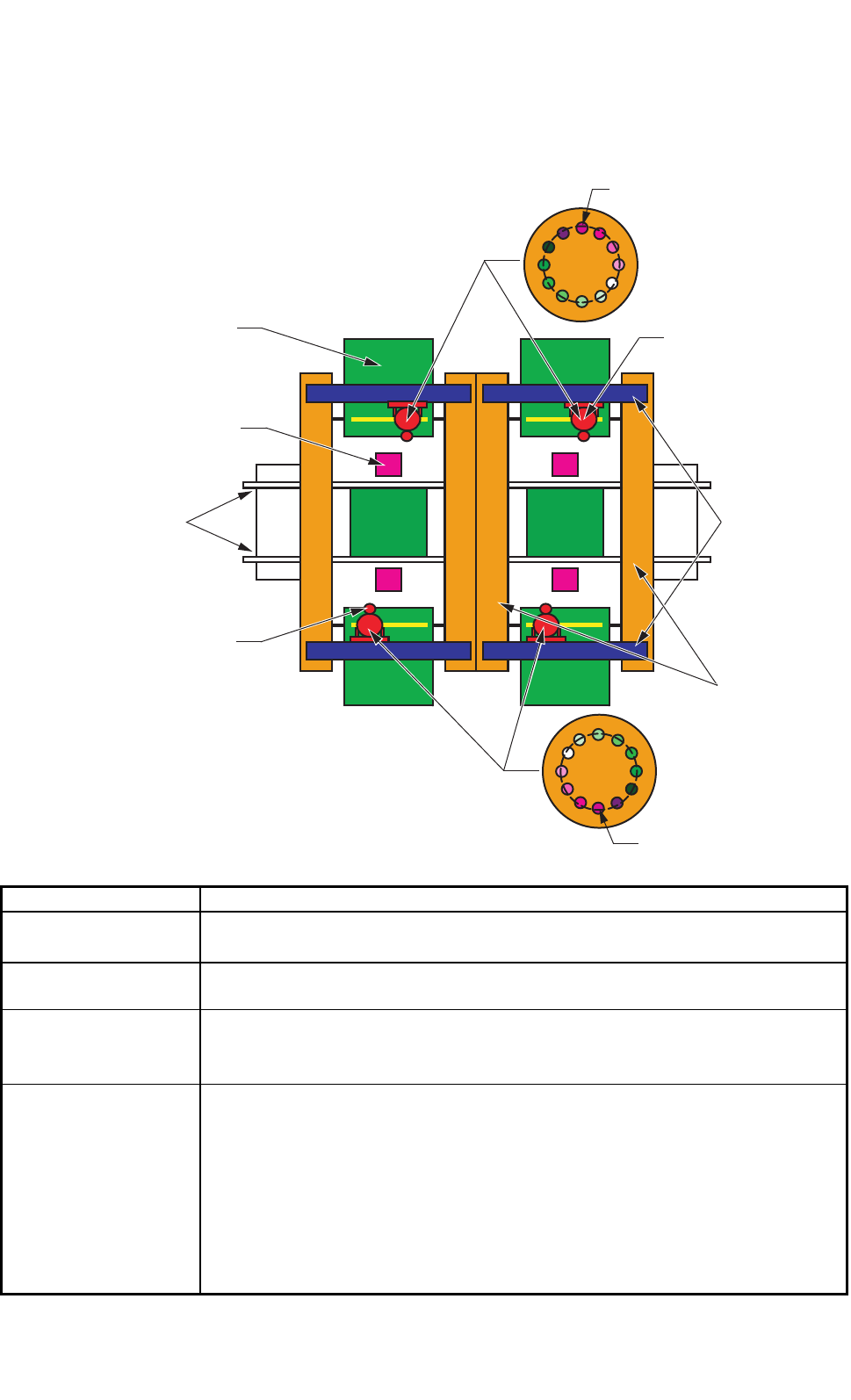
3.1.1 Mechanical Construction
Fig. 6
3.1.2 Mechanical Specifications
1. Model Name GXH-3
2. Throughput 95,000 CPH
Note : The PCB transition time under optimum conditions is excluded.
3. PCB Transfer
Time
Approx. 2.5 seconds (PCB Length: 155 mm or less) (under optimum condition)
4. PCB Flow
Direction and
Transfer Reference
PCB Flow Direction : From Left to Right ("From Right to Left" is optional.)
Transfer Reference : Front Side of Machine or Rear Side of Machine
5. Applicable PCB
Size: 50 × 50 to 460 × 460 mm (Four Corners : R1 to R1.5 mm)
Thickness : 0.5 to 5.0 mm
Warpage : 0.2 mm or less per 50 mm Max. ± 1 mm
Mass : Max. 1.5 kg (completed PCB)
Material : Glass Epoxy
Ceramic (Option)
Note : Depending on the material, shape, warpage, mass, etc., of the PCB, it is
required to make a placement test to confirm that the components can be
placed normally.
0305-002 Tg0846-WO-SP
0707-002
P.E.C Camera
PCB Transfer
Conveyor
Component
Recognition Camera
Feeder
X-axis
Y-axis
Head
Pick-Up Position
Pick-Up Position
7
SS-1189
6. Correction Method
for PCB Location
PEC Recognition
7. Conditions of PCB
before Placement
(Regulation of
Component Height)
Upper Level : Max. 12.7 mm
Lower Level : Max. 30 mm
8. Applicable
Components
(1) Applicable Components
Size : 0.6 × 0.3 to 44 × 44 mm or less
Thickness
: Max. 12.7 mm
Lead Pitch : 0.4 mm pitch or more
Lead Width : Min. 0.15 mm
Lead Length : Min. 0.20 mm
Note : Some components cannot be used due to the mechanical characteristics,
shapes, etc.
(Example of Unsuitable Components)
When there is a protruding portion on the upper surface of a component, the
lower surface of the vacuum nozzle may be worn out, causing an error during
the teaching operation through component recognition lighting.
Be sure to check the shape of the components to be used.
Applicable Components for Reference
• Cylindrical Components
Resistors, Capacitors, Diodes,
and other similar-shaped components,
• Square Components
Resistors, Film Capacitors, Coils,
Chip Ceramic Filters, and other similar-shaped components
• Deform Components
Semi-Fixed Variable Resistors, Trimmer Capacitors
and other similar-shaped components
• Ics
Mini-Flat ICs, Plastic Chip Carrier with Leads,
and other similar-shaped components
• Leaded Components
Mini-Mold Transistors, Mini-Power Transistors, Filters, LEDs, Diodes,
Coils, Tantalum Capacitors, Aluminum Electrolytic Capacitors,
and other similar-shaped components
• Connectors
Connectors for FFC / FPC, PCB-to-PCB Connectors,
Wire-to-PCB Connectors, PLCC Sockets,
and other similar-shaped components
• BGA/CSP Components (Option)
BGA, CSP, LGA, and other similar-shaped components
Size : Max. 44 × 44 mm
Ball Diameter : Min. φ 0.3 mm
Ball Pitch : 0.5 mm pitch or more
0707-002